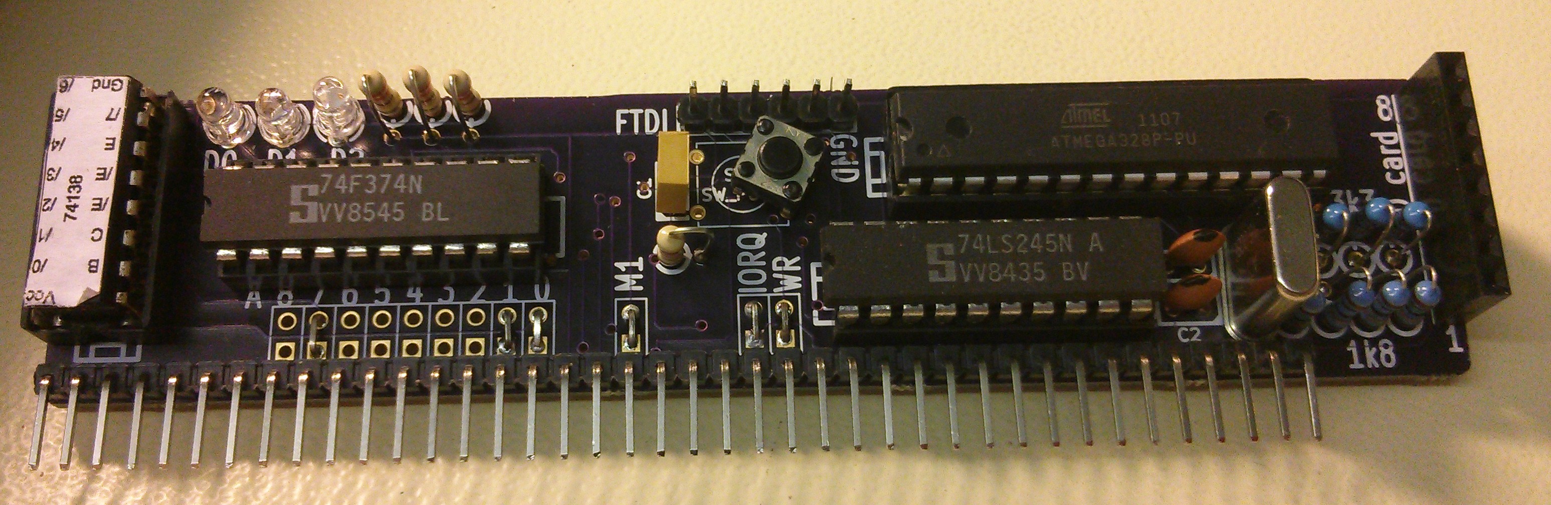
Just a quick update to about the SD Bootloader I designed a few posts ago. Well, the PCBs have arrived and last week I took a soldering iron to one of them and gave it a quick test
One side of the board is effectively an Arduino, so without plugging it in to the RC2014, I connected up an FTDI lead and uploaded the Arduino Blink sketch. A quick check with a multimeter and one of the pins was altenating between 5v and 0v. So far, all good!
Next, I uploaded a simple sketch that would count on from 0 to 255 in binary on the 8 output pin and plugged it in to the RC2014
int data_0 = 14;
int data_1 = 15;
int data_2 = 16;
int data_3 = 17;
int data_4 = 18;
int data_5 = 19;
int data_6 = 2;
int data_7 = 3;
int inbyte = 55;

void setup()
{
  pinMode (data_0, OUTPUT);
  pinMode (data_1, OUTPUT);
  pinMode (data_2, OUTPUT);
  pinMode (data_3, OUTPUT);
  pinMode (data_4, OUTPUT);
  pinMode (data_5, OUTPUT);
  pinMode (data_6, OUTPUT);
  pinMode (data_7, OUTPUT);
}

void loop()
{
  for (int inbyte = 1; inbyte < 255; inbyte++){
    digitalWrite(data_0, inbyte & 0x01);
    digitalWrite(data_1, inbyte & 0x02);
    digitalWrite(data_2, inbyte & 0x04);
    digitalWrite(data_3, inbyte & 0x08);
    digitalWrite(data_4, inbyte & 0x10);
    digitalWrite(data_5, inbyte & 0x20);
    digitalWrite(data_6, inbyte & 0x40);
    digitalWrite(data_7, inbyte & 0x80);

    delay (1000);
  }
}
A simple BASIC program on the RC2012 displayed the numbers it was reading.
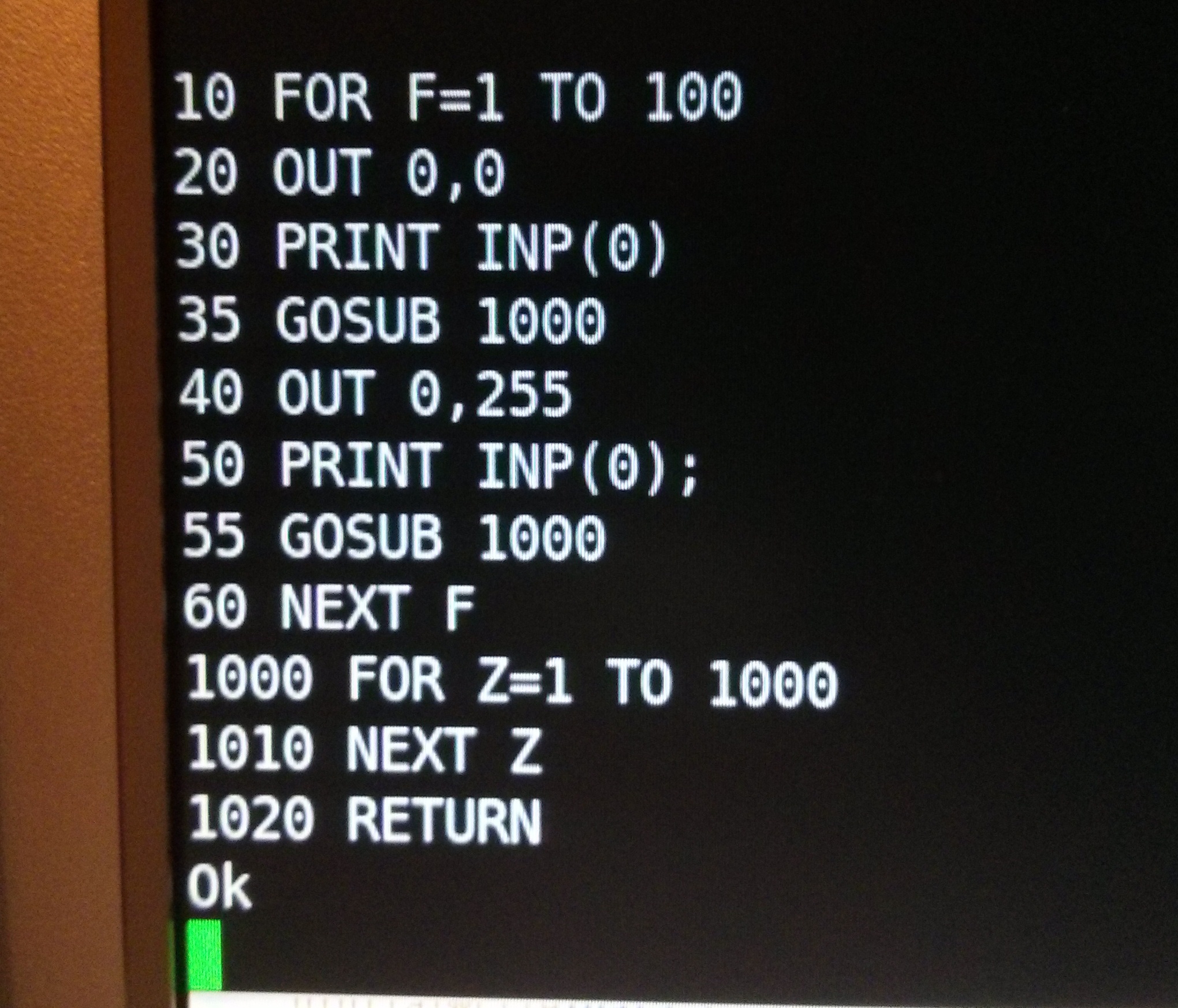
It looked like success at first, but then I realised it was counting up in a very haphazard way. After jotting down a few of the numbers in order and converting them to binary it became obvious that I’d wired up the analog pins A5 – A0 not A0 to A5. A quick change of the Arduino code and all was good there!
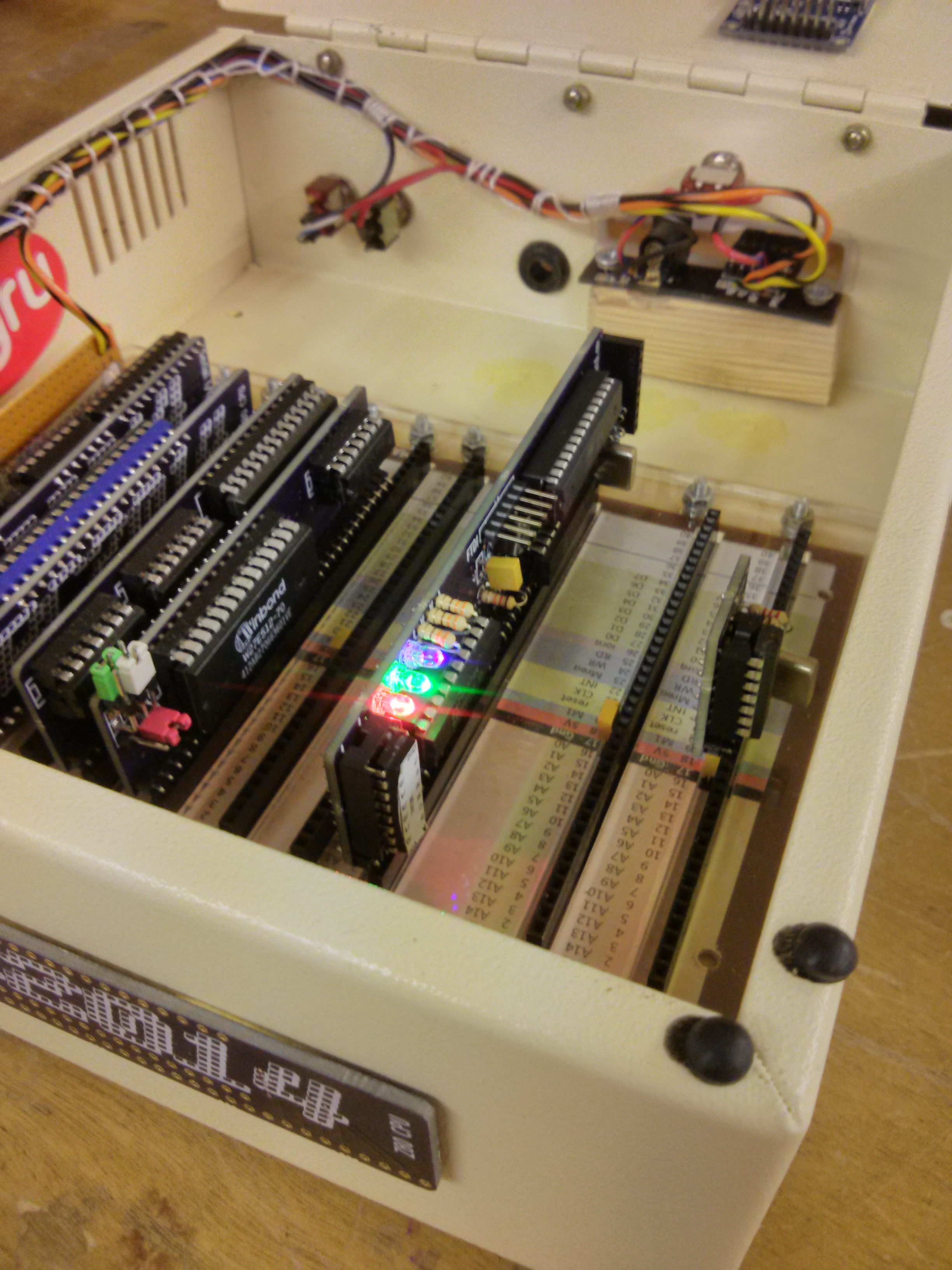
The Bootloader board has 6 output lines from the Z80, 3 of which go to the Atmel ‘328 and 3 go to LEDs. A BASIC test using OUT 0,1 OUT 0,2 and OUT 0,4 showed that the LED outputs worked, so I figured the other 3 would do too. So, next to get the SD card reading.
This proved to be harder than expected! I had designed the SD header on the end of the PCB so that it could be wired up in a few different ways. One of these was through a “poor mans SD adapter” (Simply a micro SD adapter with 0.1″ header pins soldered on!). This didn’t work, but maybe it was my soldering – I did melt the adapter a little bit! I had some cheapo chinese SD boards from eBay, so I gave on of those a go, but still nothing. Tried the other one. Nope.
I assumed that there was a problem with the new board, but to rule things out, I tried a genuine Arduino with one of the SD boards. Still nothing. Another Arduino… That didn’t work either. Maybe different SD card? No difference.
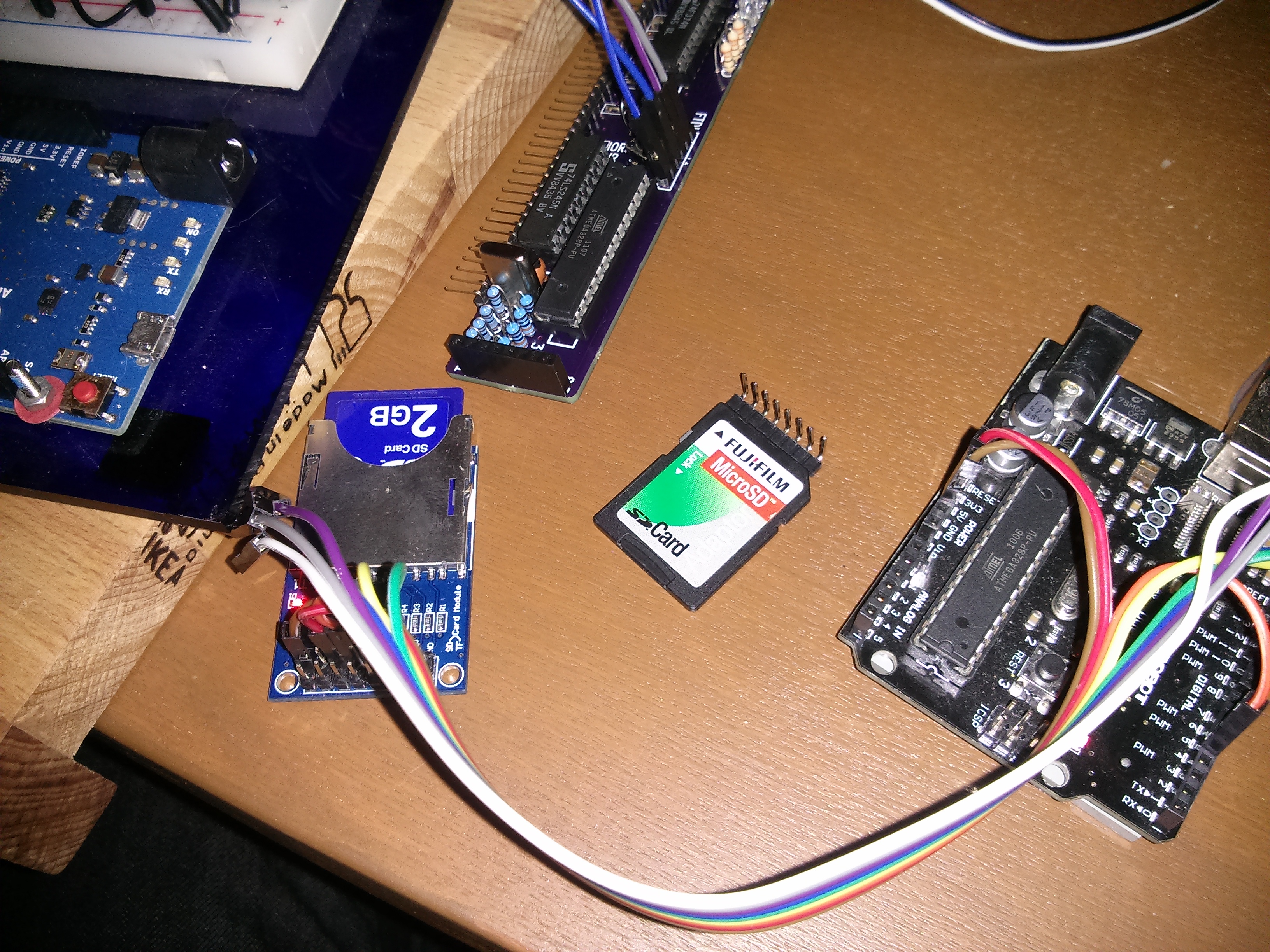
Conclusion is that all the SD adapters are dead! In the mean time, however, I did discover that using a resistor voltage divider to get the 3v3 needed for the SD card won’t work and that a proper 3v3 regulator is needed. The eBay boards have this so should have operated fine on 5v.
Then I remembered I had a faulty TFT screen with built in SD adapter. As far as I know, it’s only the screen that’s faulty, but, hey, it’s worth a try, right! And, would you believe it, it worked! About 3 hours had been wasted on faulty hardware – which wasn’t even anything I had built or designed!
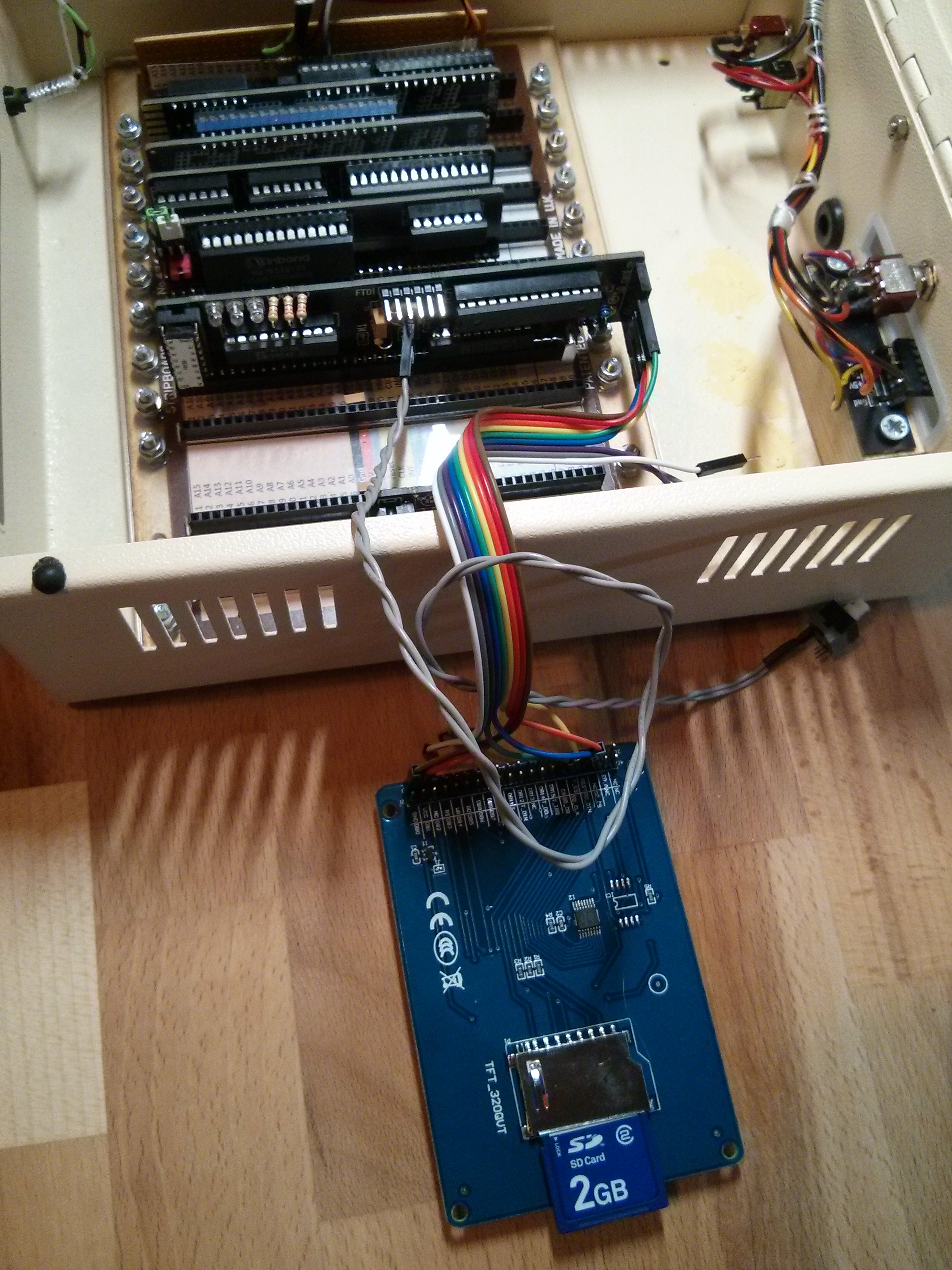
So, inspired by this, I worked on getting data from an SD card on to the RC2014. There are two sides to this; The RC2014 sets an output high, waits a moment and reads an input, sets the output low and reads the next input and so on. The ‘328 reads a byte of a file on an SD card, puts it on the output pins, waits for the input to change and reads the next byte and so on…
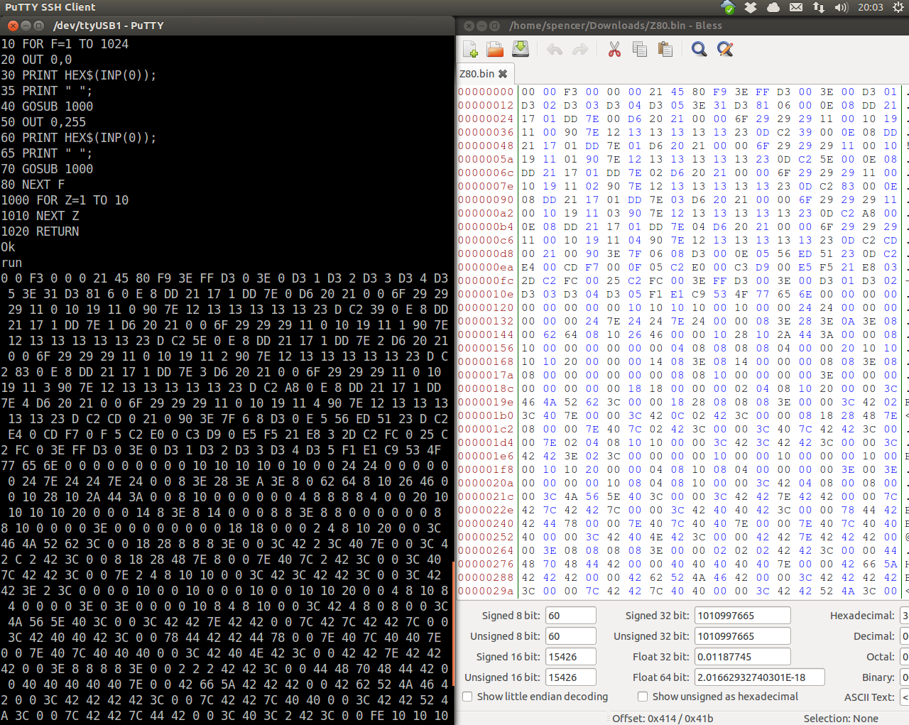
The result is that in BASIC at least, the RC2014 can read from an SD card!
The next stage is to write this in Z80 assembly language and burn it to ROM so that it can read the SD card directly in to memory and start executing the code.
In the mean time, however, I have designed my own Micro SD Card adapter for this which has a built in voltage regulator. This should make things a lot neater!