electronics (15)
Retro Challenge - Keep Calm and Solder On
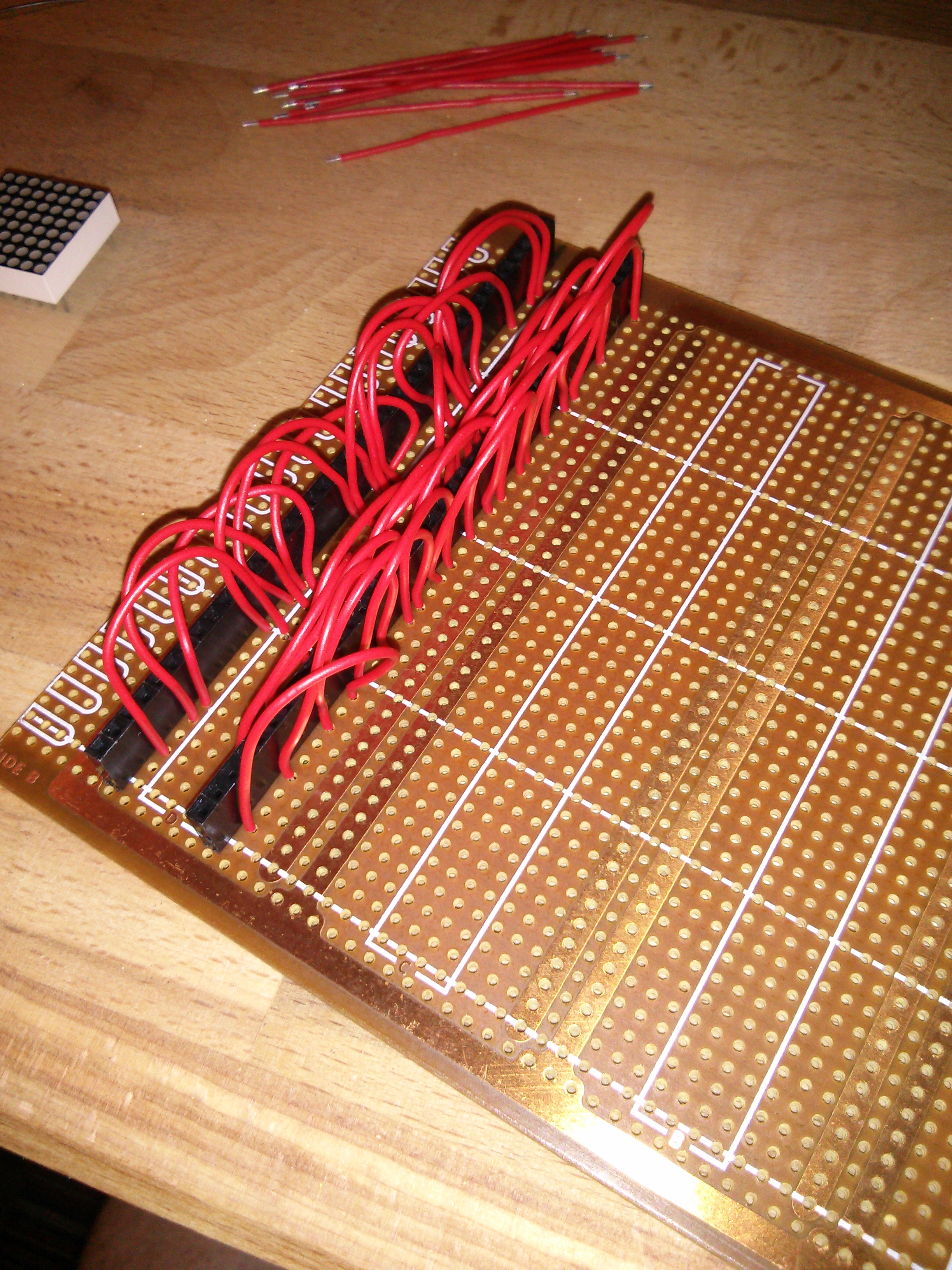
The mounting of the LED matrix has probably caused me the biggest turmoil so far on the Retro Challenge. First, I was going to design a custom PCB for them, but I missed the window of opportunity to get it manufactured at a reasonable price. So, for simplicity, I decided to use breadboard until I realised this wasn't simple with that amount of wires. So, I went back to PCB design preparing to take the financial hit. However, it proved impossible to get the tracks to fit, so this idea went in the bin again. Back to breadboard, I bought a load of jumper cables, and started expanding on what I started earlier. For the driver chips it was ok. For the matrices themselves though, I came across a show stopper; The width of it is so wide that in the breadboard there are 2 free tie points on one side but just 1 on the other. Getting a data bus down all of them was not going to be possible :-(
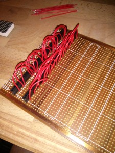
So, I had a rummage through some vintage Veroboard and found a Euro-card sized board with chip layout tracks. It would only fit 5 modules side by side, but I was prepared to make that sacrifice. I also had some 40 pin female sockets, so that made life even easier!
Retro Challenge - A Glitch In The Matrix
I knew there would be some stumbling blocks with this Retro Challenge, but, hey, it wouldn't be a challenge if everything was just nice and simple. However, I seem to be beset by little stupid technical issues that aren't necessarily retro in nature.
However, the fact that you're reading this does at least mean that my blog is working again! I ran some updates last week, and it caused some issues with a plugin meaning I had no way of adding, editing or modifying any posts. I've now got that tracked down to the Poll plugin and disabled it. So, yay, I'm back!
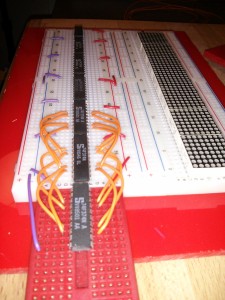
So, part of this challenge is to use LEDs, and the little 8x8 matrix modules I found seem ideal. I had initially intended to design a PCB to mount a bunch of these on, but due to time constraints, it was looking very unlikely I'd get them designed, ordered, manufactured and delivered by the end of the month, let alone time for testing. So I decided to go Old Skool, and do this part on a breadboard. Well, 2 breadboards, as they each need a driver chip. Although, it's actually 3 breadboards, as 2 aren't quite big enough. Not to mention the other breadboard with the supporting circuitry on. I made a start on this last night;
Retro Challenge - The inbetween days
So, after a flurry of activity, blog posts and updates at the start of the month, things have got a bit quiet.
That's not to say I haven't been doing anything. I have. Lots. But nothing really specific or bloggable.
Until the batch of PCBs arrive, I am kind of in limbo land. However, I've been looking in to the LED matrix boards a bit more, and working out how I'm going to connect them up (short answer - use breadboards to complete the challenge, but get PCBs made up for long term mounting.).
As the breadboard Z80 runs Microsoft Basic, I have been using that to test out a few bits in terms of orientation of the matrices and the best way to drive them.
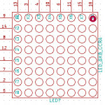
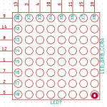
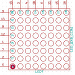
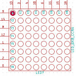
Retro Challenge - Getting inside the matrix
So, today I finally did some hands-on retro wires and programming stuff instead of sitting at a PC doing CAD stuff.
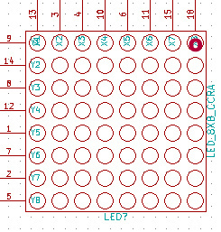
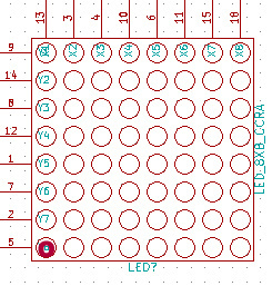
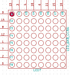
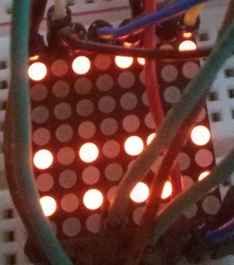
I thought I knew how the LED matrix modules would work, in theory, but before I commit anything to copper and fibreglass, I'd like to test things out a bit. So I dug out my breadboard Z80 and fired it up to check it still worked (it did), and refreshed my memory on how the BASIC "OUT" command works with the '374 latches. Finding a bit of space on a breadboard, I plugged one of the modules in and wired it up in place of the bar graph and 7-seg displays I'd previously used as channel 0 and 1
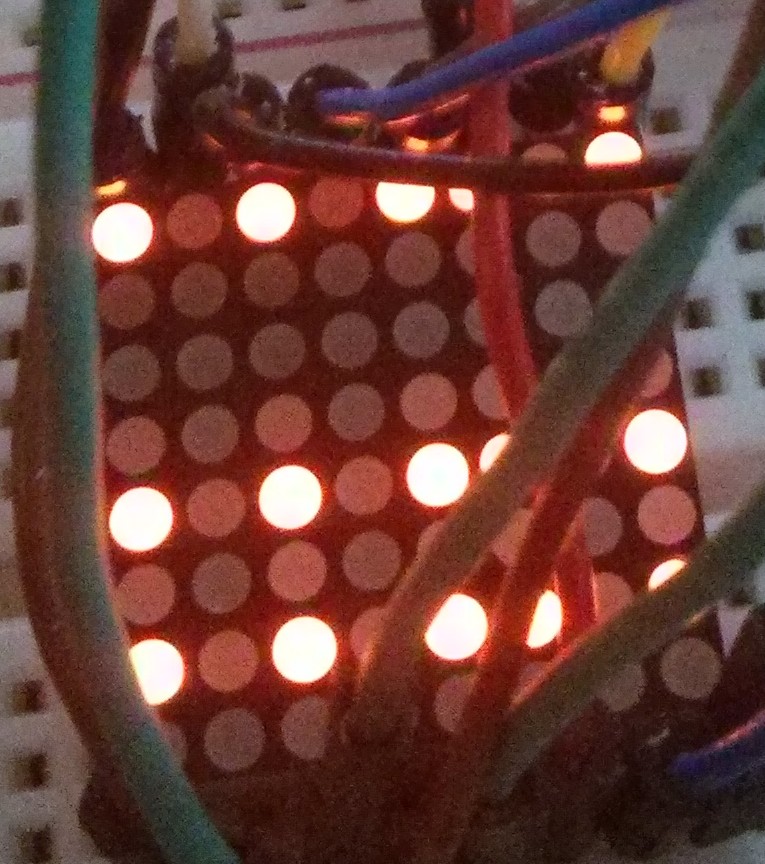
I wanted to get a single dot on the display, so that meant turning the various pins high or low. One channel needed a single pin high with the other channel all high except for one pin. Or the other way around. Or just one pin on both channels. Or, maybe all high except for one on both channels. I could have gone through and calculated exactly which combination to use, but it was quicker to try everything. But I got very weird results
Retro Challenge 2014 - Day 5 - First PCBs Ordered
Hokey cokey, that's the first 4 printed circuit boards for the RC2014 (Oh, did tell you I've named my homebrew Z80 computer "RC2014"? Pretty catchy name, eh?) ordered with OSHPark. If they arrive as quick as other boards I've had from there before, then I should have 11 days to get everything put together and working!
All 4 boards look fairly similar, being a CPU board, RAM and 2 variation on ROM, but here's the 32k RAM board;

Pre-RetroChallenge - The story so far
Ok, so tomorrow the Summer RetroChallenge 2014 starts, so I thought it would be a good idea to bring you up to speed with what I've got so far so that you know where I'm starting from. I will also outline where I'll be taking things for the RetroChallenge as well as where this project may go in the future.
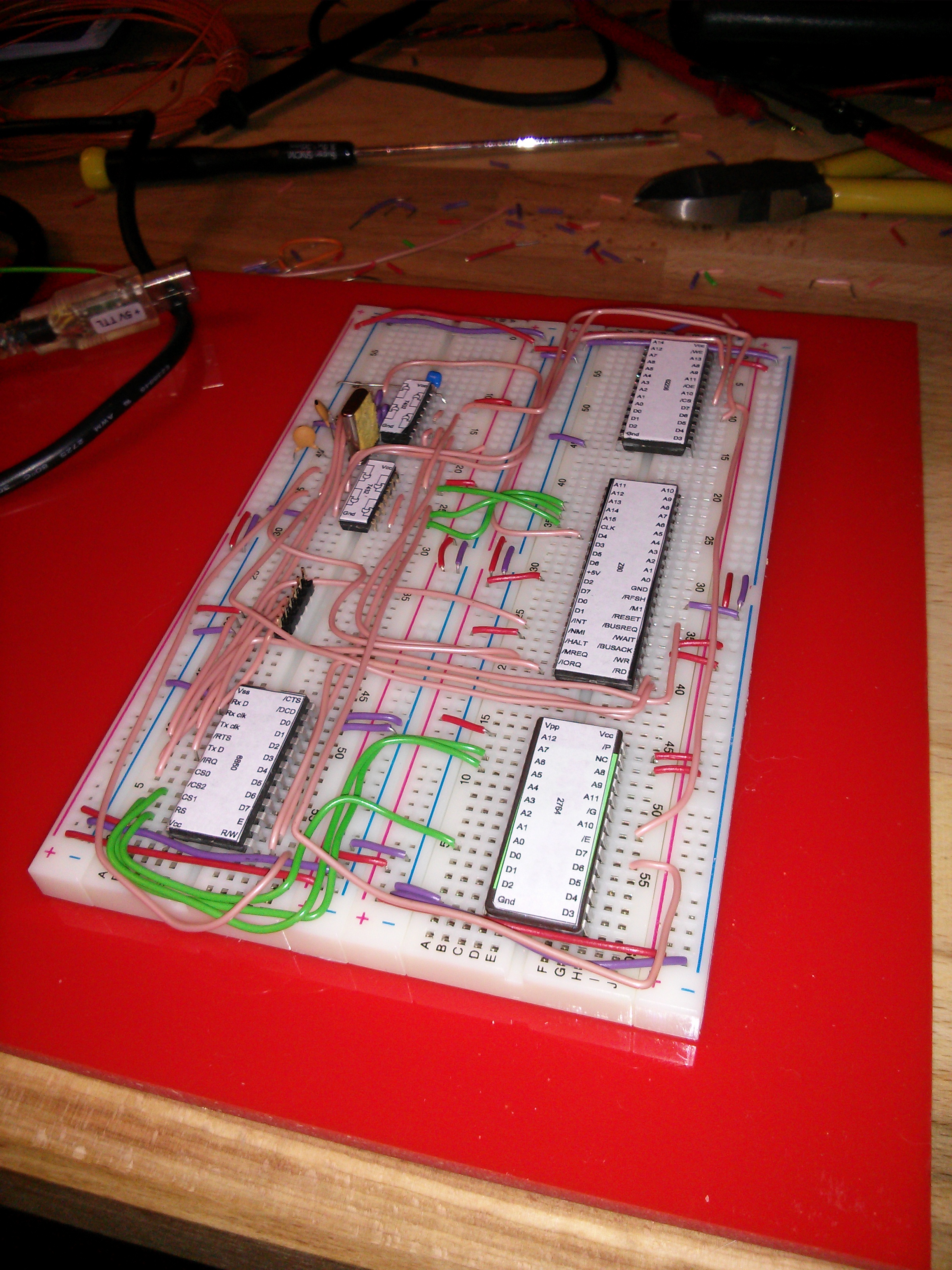
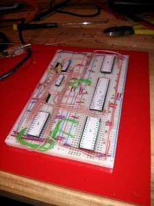
So, in December 2013 I started poking around the internets for some ZX80 info, and I stumbled upon Grant Searles website. More specifically, he had the schematics for a Z80 based computer and a ROM with Microsoft BASIC on it. So, over Christmas I got out my breadboards and built it up pretty much as per the schematic.
Retro Challenge 2014
I have always wanted to enter Retro Challenge, ever since I first heard of it nearly 24 hours ago. I followed a link that took me to http://retrochallenge.net/ and I read up on what it was all about, scrutinised the rules and checked out what others were doing. I quickly came to the conclusion that I could give this a thing a go.
All I needed to do* was come up with a suitable challenge for myself.
I have decided to make my name appear in LED lights.
So an email was sent to the competition organisers;