The backplane support plate and front panel assembly are not difficult to put together, but there is an order to things that can make your life easier.
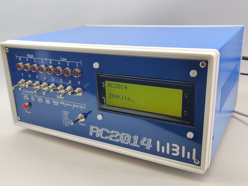
The illustrations below show a fairly minimal RC2014 Zed Pro. Your exact kit will probably vary or have other modules in it. Whichever kit you have though, it is highly recommended that you build and test it before fitting it inside the enclosure as troubleshooting (if required) will be a lot easier that way. Also please be aware that I do not manufacture the enclosure itself, so it may be subject to changes or tolerances that are out of my control. If you find that something really isn’t going to fit, please get in touch and I am sure we can find a solution.

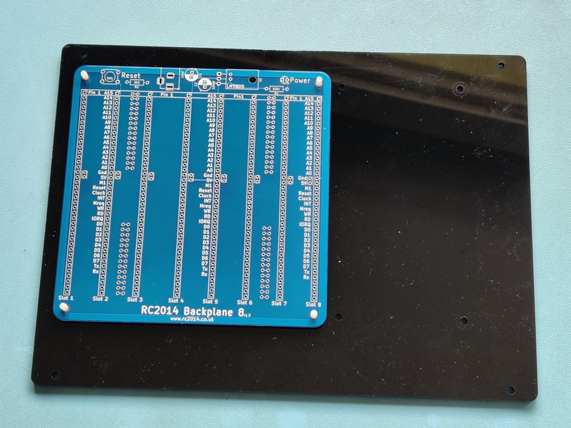

First, start with the backplane support plate and identify which holes match the backplane you have. A Backplane Pro, Backplane 8 and a Backplane 5 will fit. Note that the backplane sits towards the left and rear of the enclosure, so there should be a smaller gap along the side by Slot 1 and the rear (where the power jack etc) are. If that is not the case, try turning the support plate the other way up.


A Backplane 8 can be coupled with a Backplane 5 too with right angle pins and socket – although you will need to source an additional couple of fixings.
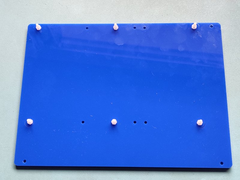

Once you have identified the correct holes, remove the protective film, insert a 12mm nylon screw from below and fix it in place with a nylon nut. This gives around 2.5mm clearance under the backplane for the solder joints. This should be sufficient, but you may need to trim the tabs off of the barrel jack socket.


Next, remove the 4 screws each holding the front and rear panels on the blue box and the 4 screws holding the top/side cover. Make a note of which screws are which as they are different lengths.
Then remove the two M3 nuts and screws holding the bottom panel on, and loosen slightly the corresponding nuts on the other side.
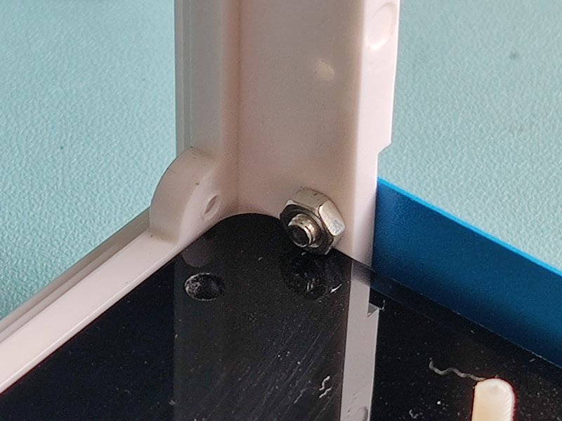
Insert the support plate by going in at an angle, then tucking it under the nuts you have just loosened and lay it flat. Reinsert the nuts and screws and tighten them all up. You should find that the support plate fits snugly under the nuts without any other fixings.


Now you can fit your backplane and modules. Leave Slot 1 and Slot 12 free and do not fit the LCD Driver Module or Front Panel Module at this stage. Fix the backplane in place with nylon nuts.


Prepare the front panel by fitting the LCD display and Front Panel assembly. See separate assembly guide for the front panel switches and LEDs. For the LCD display, insert 4 nylon screws from the front and fix in place with nylon nuts. Add a second nut with a couple of millimeters gap so that the display bezel is flush with the panel. Finally use the last 4 nuts to hold the display in place.
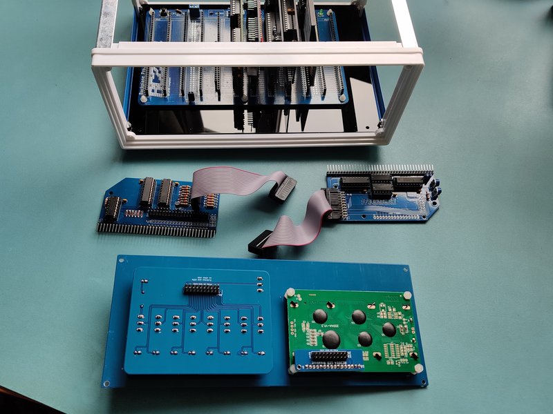


It is slightly easier to fix the 2×10 ribbon cables to the switch panel and LCD first, then fit them to their appropriate modules. Ensure the the red line on the cable goes towards the Pin 1 marking at both ends. Reuse the screws you took out of the front panel when you disassembled it to hold in the new front panel. Fit the two modules in to your backplane in to Slot 1 and Slot 12
If you have a rear panel kit too then this is the time to fit it. Note the photos below are an early prototype rear panel and used as a placeholder for now.


The lid can now be refitted using the screws you removed earlier. Good work! Now load up a game of Zork to relax.