The primary goal of Retro Challenge was to write my name in LED lights. Although not really a part of the RC2014 computer directly, I’ve included it here probably more for curiosity sake than anything else. Although it does work, my advice to anyone is to not do what I did i.e. wiring up 5 LED matrixes and associated drivers on a prototype board. It gets very fiddly and hard to debug very quickly.
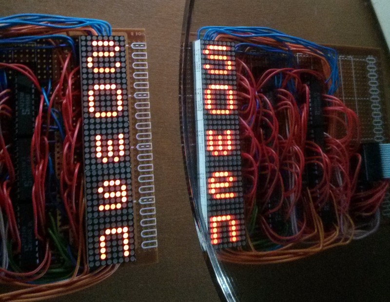
One of the quirks was that the x and y had been transposed, and when I programmed it, the writing came out mirrored. This could have been fixed in software, or fake-fixed by flipping the image in Photoshop… but I found that an actual mirror gave me the desired effect with minimal effort.
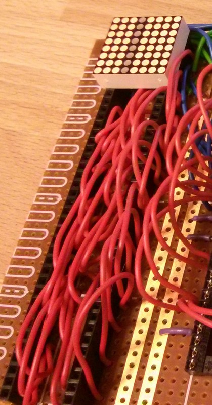
This was part way through construction with only the X (or was it Y) coordinates and one LED wired up. As you can see, the trench under the matrix is already very full
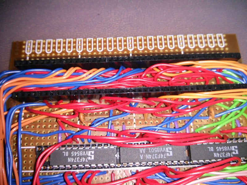
With all the wiring in place it was very tight to push the LEDs in to place. There are 2 dodgy connections in there somewhere. I’m not sure where, but giving it a jiggle seems to fix one or the other (or occasionally both) of them.
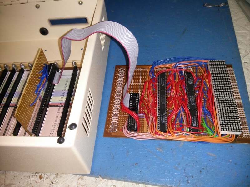
The board is pretty full with 5 LED matrices, 7 chips and the interconnect. Connection to the RC2014 is just via a simple adapter.
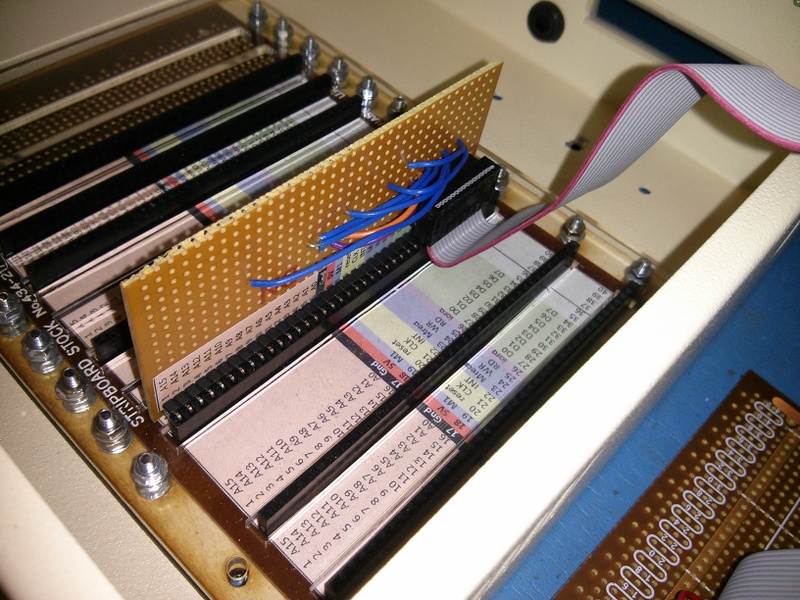
Power, 8 data lines, 3 address lines (A1, A2, A7), M1, IORQ and WR come off the RC2048 backplane

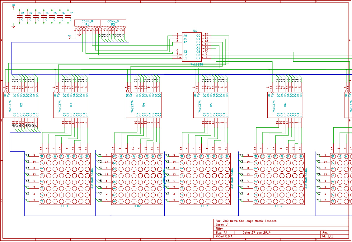
Below is something that resembles the schematic of what I built. I honestly don’t know if the X and Y are transposed, and the data 0-7 could also be reversed too, but I’m not inclined to dig through the rats nest of wires to check. Click the schematic to download pdf
The assembly code I used to run it can be found on this blog post
One day I might redo this on to a PCB, and when I do, I’ll provide a lot more detail
Leave a Reply
You must be logged in to post a comment.