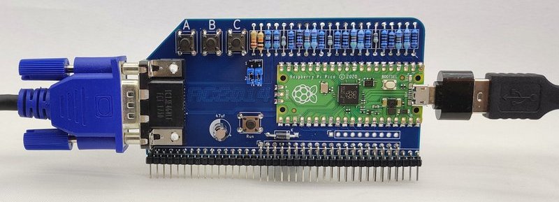
The Pi Pico VGA Terminal is a simple terminal for the RC2014 to allow it to be used standalone. It connects to a regular VGA monitor and accepts a USB keyboard. It is designed as a simpler alternative for the Pi Zero Serial Terminal
The Hardware
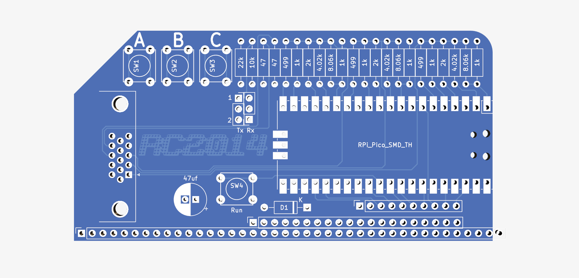
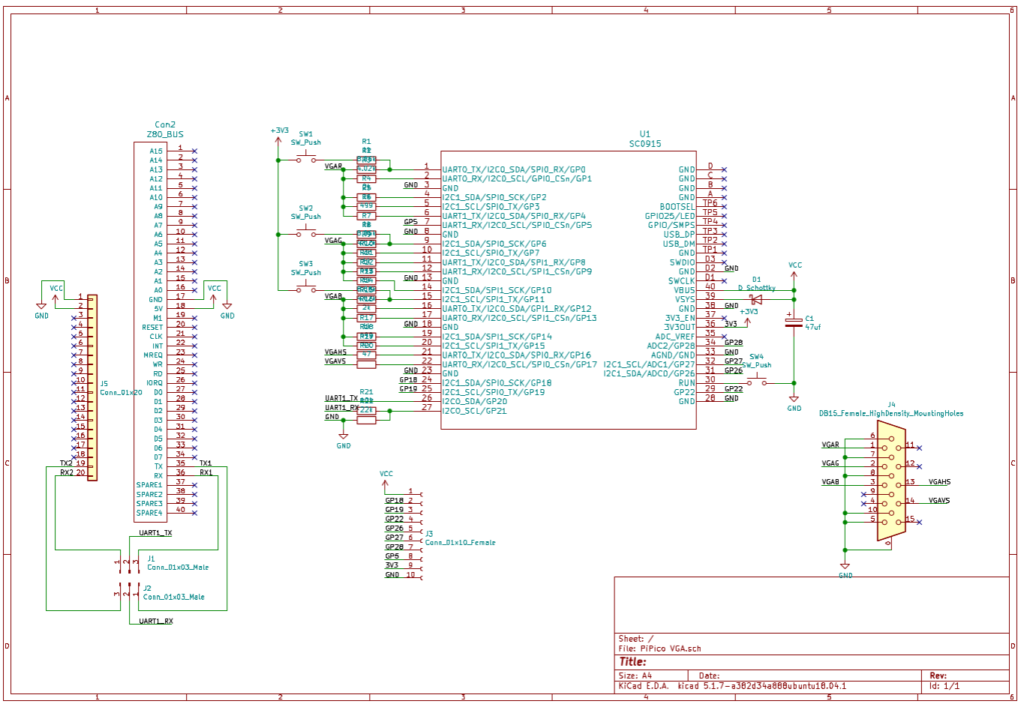
This module uses the Raspberry Pi reference design as found in their Hardware Design With RP2040 document to generate a VGA signal. This essentially uses 5 precision resistors for each of the red, green and blue channels as a digital to analog converter. These 15 resistors are connected to the GPIO pins of the Pi Pico. With 5 bits per colour, 32768 colours are theoretically possible. 2 other GPIO pins are used for the H-Sync and V-Sync.
The reference design also included 3 buttons connected to the least significant bit of each colour. While writing a scanline to the screen, pushing a button will have a barely noticeable effect on the picture. However, while the H-Sync or V-Sync signals are being generated, the GPIO pins for the switches can be set as input and the state can be read. This has no immediate application for this Pi Pico VGA Terminal, however, it has a very minimal cost to include, and may, at some point, be useful. For example, changing the baudrate, a simple menu system, or replaying a stored serial string.
The Tx and Rx from the RC2014 connect through two jumpers. This allows either UART1 or UART2 on the RC2014 to be used. The GPIO of the Pi Pico is not 5v tolerant, so the Tx from the RC2014 goes via a simple resistor voltage divider to bring it down to the 3v3 acceptable to the Pico. The 3v3 Tx from the Pico is above the threshold needed that it can be heard by the SIO/2 or MC68B50 of the RC2014. Note that if you wish to use this for VGA output only, and not USB keyboard input, the Tx jumper should be removed.
The Pi Pico is powered from the RC2014 bus. A Schottky diode on the Vsys pin of the Pico allows it to safely be connected to both a live RC2014 and powered from a USB cable too.
There are just a few unused GPIO pins on the Pico. These do not currently have any function on this board, but it seemed only polite to bring them out to pads, along with 5v, 3v3 and Ground.
The Software
PicoTerm is a terminal emulator written specifically for this module. Currently it runs 80 columns by 30 lines in black and white mode. Switching to 40 column colour version will be available shortly. It can use VT100 style escape codes, with support for the following
\ESC[?25l | Cursor invisible
\ESC[?25h | Cursor visible
\ESC[H | Move to 0-0
\ESC[s | Save the cursor position
\ESC[u | Move cursor to previously saved position
\ESC[-Row-;-Col-H | Move to -Row-,-Col-
\ESC[0K | Clear from cursor to the end of the line
\ESC[1K | Clear from the beginning of the current line to the cursor
\ESC[2K | Clear the whole line
\ESC[2J | Clear the screen and move the cursor to 0-0
\ESC[-n-A | Move the cursor up -n- lines
\ESC[-n-B | Move the cursor down -n- lines
\ESC[-n-C | Move the cursor forward -n- characters
\ESC[-n-D | Move the cursor backward -n- characters
\ESC[0m | normal text (should also set foreground & background colours to normal)
\ESC[7m | reverse text
\ESC[0J | clear screen from cursor
\ESC[1J | clear screen to cursor
\ESC[3J | same as \ESC[2J
\ESC[nS | scroll whole page up by n rows (default 1 if n missing)
40 col colour only: (sequence is ignored, no effect in 80 col b/w)
\ESC[38;5;-n-m | Set foreground colour to -n- (0-255)
\ESC[48;5;-n-m | Set background colour to -n- (0-255)
USB keyboards are supported via a USB OTG adapter – however, not all keyboards currently work. Most cheap generic keyboards seem to work fine, however, the testing sample is still fairly small. Hopefully with more data it will be easier to identify exactly which keyboards are likely to work and which aren’t, or, better still, a simple software fix will get more working.
The source and compiled binaries for PicoTerm and PicoTerm Colour on GitHub
Programming Firmware
The Pi Pico uses a UF2 bootloader to appear as a mass storage device so that new firmware can be uploaded to it. To do this, connect a Micro USB lead between the Pico and your PC/Mac/Laptop/Raspberry Pi/Android Phone. Then push the BOOTSEL button on the Pico. Whilst holding this down, push and release the RUN button on the VGA board. (Trust me. This is easier to to than to put in to words!). The Pico will then show up as a drive on your computer. Simply drag and drop the UF2 firmware on to this drive. The Pico will automatically reboot and disconnect once this is complete.
Some tips on soldering the Pi Pico module to the PCB can be found here

Bill Of Materials
1 RC2014 Pi Pico VGA PCB
1 Raspberry Pi Pico
1 RA VGA socket
4 tactile switch
1 47uf 25v electrolytic
1 40 pin RA header
2 3 pin header
2 jumper
3 8k2 resistor metal
3 3k9 resistor metal
3 2k resistor metal
6 1k resistor metal
3 510 resistor metal
2 47 resistor metal
1 1N5817 Schottky Diode
1 10k resistor
1 22k resistor