The ESP8266 Wifi Module allows the RC2014 to be connected to a Wifi network, either as a serial link, or to publish the RC2014 on the internet, or connect to BBS sites.
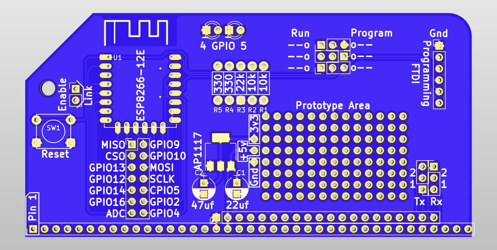
An ESP8266 ESP-12 module lies at the heart of this. It is powered from a 3v3 regulator. For regular use, the Tx and Rx pins are connected to the RC2014 and, enable pin is pulled high and GPIO0 (program) is also pulled high. Two LEDs are connected to GPIO4 and GPIO5 to allow for Wifi Connected and Data Activity notification,
The GPIO pins are all bought out to pads and a prototype area will allow you to take advantage of the ESP8266 power to do more interesting stuff.
An FTDI header, along with selection jumpers allow the ESP8266 to be reprogrammed with a standard FTDI cable and either the ESP8266 SDK or the Arduino IDE.
The operation of the module is very simple, and configuration falls in to two categories; jumper connectivity and firmware.
Firmware
The firmware preinstalled on the ESP-12 module is ESP-Link from JeeLabs. This allows the RC2014 ESP8266 Wifi Module to operate as a wireless serial link so you can telnet to your RC2014 from another PC on the same network. Configuration of this firmware is very quick and simple, as shown in this guide.
The other firmware that has been tested with this is WebSocketSerialMonitor from tzapu. With a slight modification as shown here and the addition of Wifi Connected and Data Activity LED control, it allows you to broadcast the output from the RC2014 to the internet. If Twitch.TV was around in the early 80’s, it would probably work like this :-)
There are a lot of other ESP8266 firmware images that should also work with this, allowing you to control Wifi devices, log info to MQTT servers, or connect to any of the many internet based BBS sites.
Jumpers
The Tx from the ESP8266 and Rx to the ESP8266 are routed via jumpers, and will determine how your Wifi Module works.
Primarily, it is expected that you connect both the Tx and Rx to UART1 of your RC2014. This will allow your Wifi Module to operate as a wireless serial link with the ESP-Link firmware. The 3 run/program jumpers should all be set to the left (Run) and the Tx and Rx jumpers put in the lower position.
The module is supplied with both a single row header for 68B50 based RC2014 machines, and also a double row header for Backplane Pro & SIO/2 based machines. So, if you are using a SIO/2 Dual Serial Module, you can connect to UART2 by moving the Tx and Rx jumpers up to the higher position. From CP/M you can select which UART is used for what input or output. See Grant Searles page for a bit more info on how the IOBYTE is used.
You might, however, only want to transmit or only want to receive, such as using the WebsocketSerialMonitor firmware. In which case, simply remove the Tx or Rx jumper accordingly.
Note that the 68B50 and SIO/2 UARTs can transmit to many devices, but only receive from one. So, whilst it is possible to use the Pi Serial Terminal Module to display data on a monitor and use the ESP8266 Wifi Module as a wireless serial link, you cannot also use the Pi Serial Module for keyboard input at the same time.
To reprogram the ESP8266, the 3 run/program jumpers should be moved to the right (program). This redirects the Tx and Rx to the FTDI header, and pulls GPIO0 low to put it in to programming mode. Push the reset button before uploading your new firmware. After reprogramming, put the jumpers back to the run position.
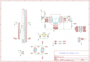

Important note for v1.1 modules – R2 is shown as 10k on the silkscreen. A 1k resistor should be used here, not 10k. The v1.1 schematic is here

Bill Of Materials
RC2014 ESP8266 PCB
ESP8266 Module
40 pin RA Header
40×2 RA Header
3mm Red LED
3mm Green LED
3v3 Regulator
22uf 25v electrolytic
47uf 25v electrolytic
330r resistor x 2
22k resistor
10k resistor x2
Tactile switch
6 pin Header
3 pin Header x 5
Jumper x 5