When it comes to connecting modern mass storage devices to old 8 bit computers, the humble compact flash card is ideal. It normally presents itself as a 16 bit IDE drive, although it is quite happy to run in 8 bit mode, and even a small CF card by modern standards can hold a huge amount of data.
The v2 Compact Flash Module builds on the Compact Flash v1 modules, but addresses the limitation with card compatability on some Compact Flash cards. V1 played a bit loose and fast with the timings it presented to the CF card. Whilst this was fine with a lot of cards which were quite tolerant of timing issues, there were some cards which were much stricter and adhered to the Compact Flash Specs too closely.
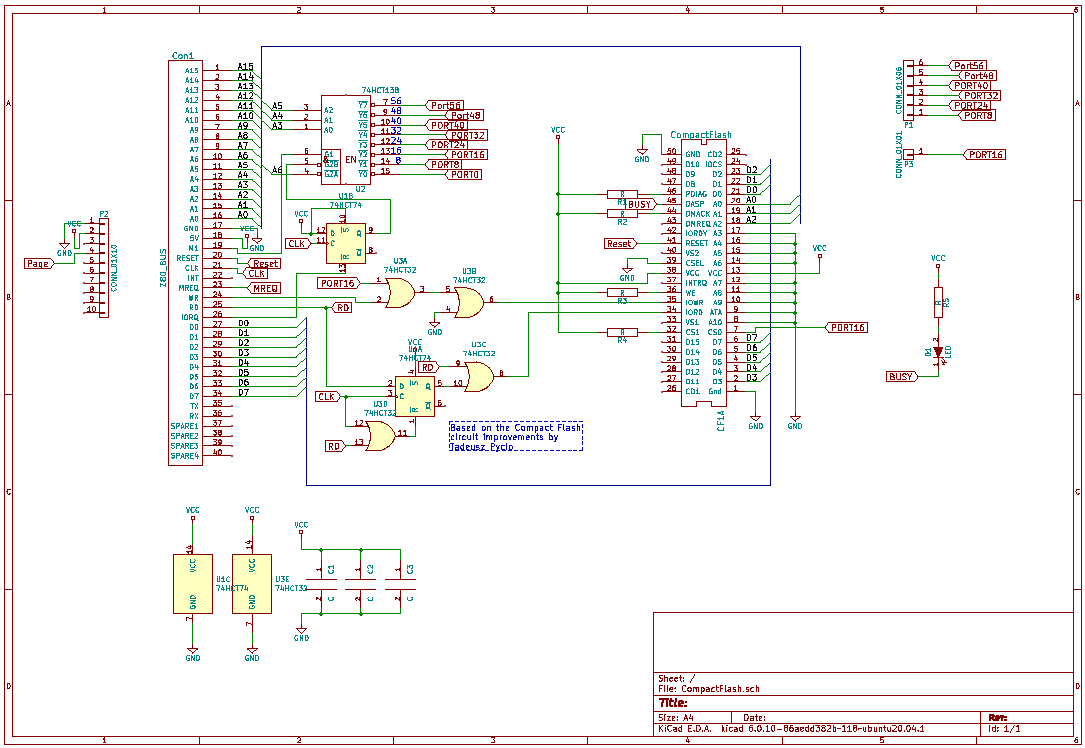
The enhanced circuit was developed by Tadeuzd Pycio and full credit goes to him for allowing the RC2014 Compact Flash Module to work with a much greater range of CF cards. For a detailed explanation of how CF timing works and the enhancements made, please see http://www.vtsys.pl/interface-compact-flash/ (Google Translate does a great job if you aren’t fluent in Polish)
Aside from the IORD, IOWR and CS0 signals, the rest of the module is the same as the V1 module.
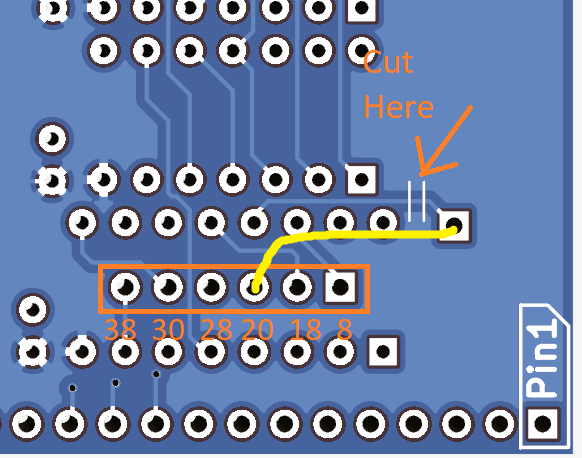
It is, however, now easier to select a different address for the module to sit on. In normal use it will appear on 0x10, which is the standard address for Grant Searles version of CP/M and also RomWBW. 99% of users can stop reading here as there is nothing you need to do. However, if adding a 2nd card, you will need to put it on a different address. To do this, there is a track on the underside of the board, next to the ‘138 with some lines to guide you where to cut. Then a jumper wire should connect the pad labelled CS0 next to it to one of the pads to select the address as indicated below. Note that 0x20 is also recognised as a secondary CF address in RomWBW
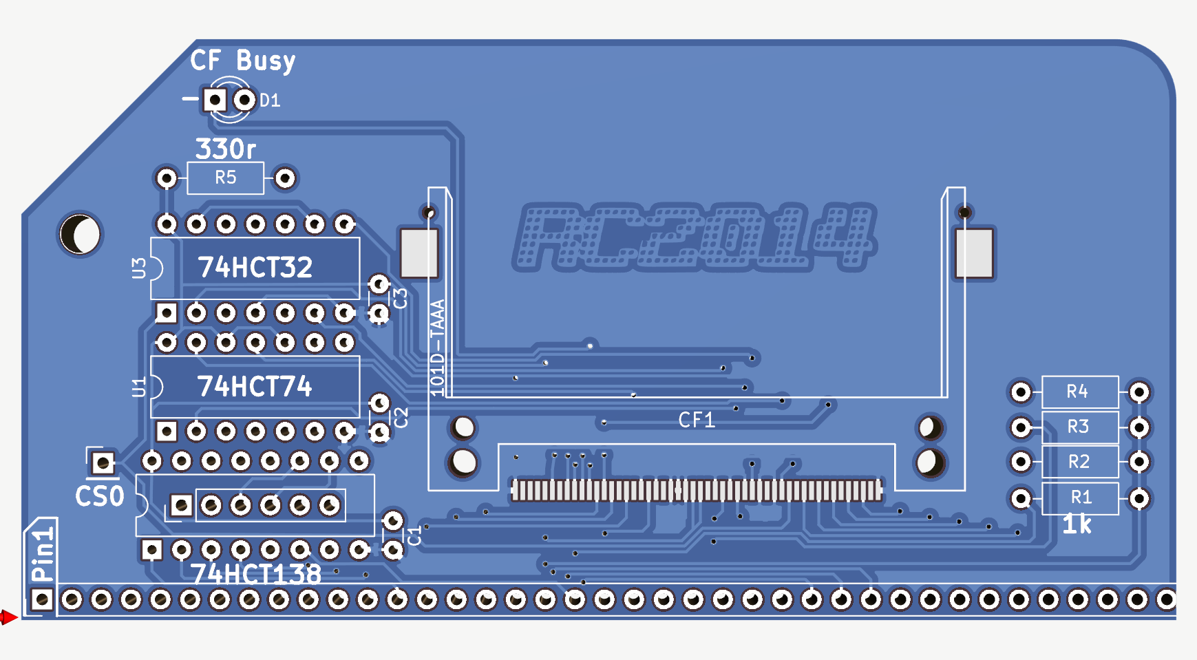
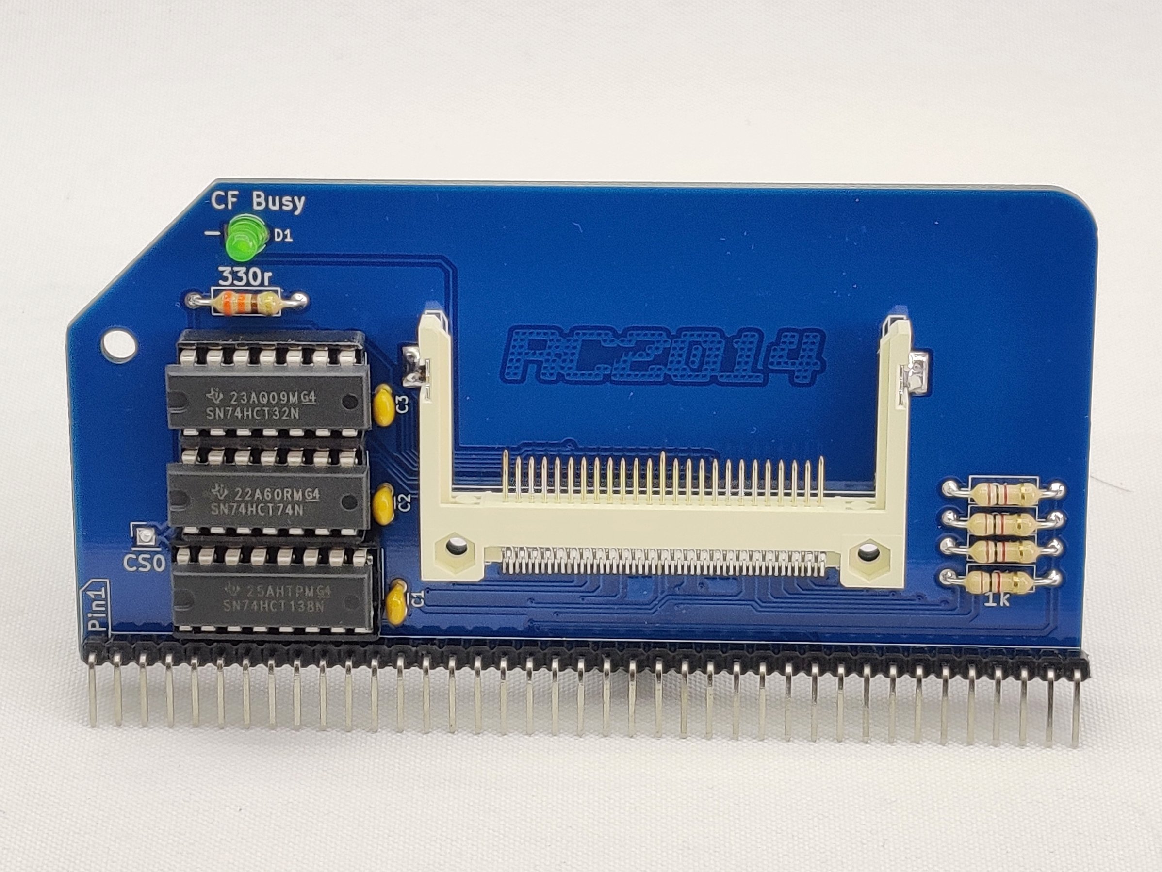
Assembly of the module is fairly straight forward with only 13 components – however, due to the compact flash socket being a surface mount component with pins at 0.025″ (0.635mm) pitch, great care must be taken to avoid solder bridges with this. There are a couple of tiny lugs on the back of the CF socket that locate it exactly on the PCB though, so it should stay perfectly lined up whilst soldering. The cathode on the LED is indicated with a – symbol.
For a guide on running CP/M on Compact Flash, see this page.
The files needed can be found on Github

Bill of Materials
- RC2014 CFLASH PCB 1
- Compact Flash Socket 1
- 40 pin RA Header 1
- 16 pin narrow DIL socket 1
- 14 pin narrow DIL socket 2
- 100nf 3
- 74HCT138 1
- 74HCT32 1
- 74HCT74 1
- 330R resistor 1
- 1K resistor 4
- 3mm Green LED 1