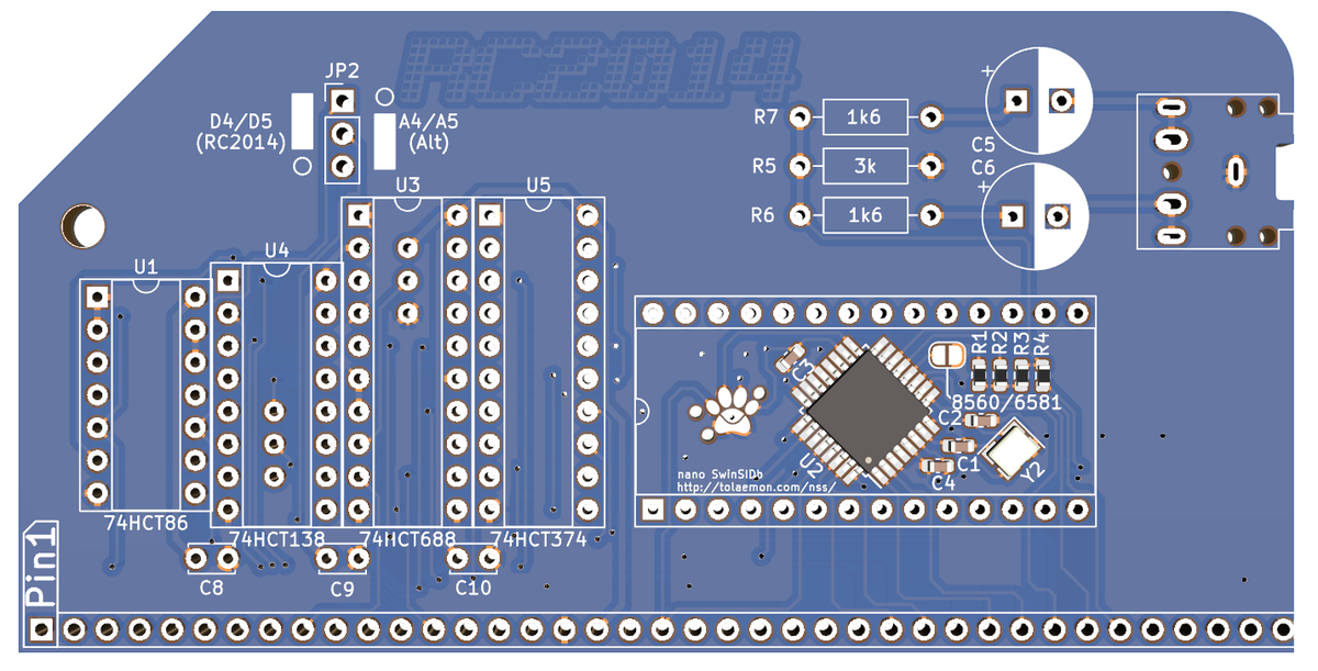
The SID-Ulator Sound Module is a sound card for the RC2014 based around the nano SwinSID b emulator. This firmware emulates either a MOS6581 or MOS8580 Sound Interface Device – or SID chip. It has a simple addressing scheme with standard ports on D4/D5 or alternatively A4/A5. The pre-soldered SMD components can be disguised with an optional 28DIP IC. Audio output is via a 3.5mm headphone jack.
This module uses an addressing scheme based around the Why Em-Ulator Sound Module so that both can coexist together. An ATMega88 emulating the now rare and expensive SID chips has the benefit of not relying on hardware that went out of production decades ago.

Click image to open PDF schematic

Assembly
Assembly is pretty straightforward, and similar to most other RC2014 modules. Start with the lowest components and work your way up. The ICs and IC sockets have a notch in one end which should line up with the silkscreen. The large electrolytic capacitors should also be lined up so the white stripe aligns with the white marking on the PCB.
The 28 pin DIP socket is optional. You can use this to mount a dummy chip to hide the surface mount components. None of the pins are connected to anything, so no damage will be caused to either the chip or the components. This is a great place to mount a non-functional SID, but any chip can be used. Why not use an AY-3-8912 and prank your friends!
Note that whilst the solder-blob-jumper to select between 8580 and 6581 can be accessed after the 28 DIP socket is installed, it is easier to do so beforehand.
Hardware
The addressing is handled by an ’86, ‘138 and a ‘688. Firstly, the ’86 XORs A6 with A5 and also A6 with A4. This means that the 010 and 101 pattern formed in the port address D4/D5 and A4/A5 can be identified. (It will also identify ports 54/55 and 24/25 too. More on that later). An ‘866 comparitor is then used to look at A7, A3, WR, M1 and IORQ. If these match the levels on the other side of the ‘866 then the ‘138 !E0 will be enabled. !E1 is tied to ground, thus already enabled. And E2 is enabled by either A4 or A5. This will determine if the D4/D5 or A4/A5 addressing is used. The output of the ‘138 is determined by address A0, A1 and A2. This logic will give 8 possible outputs, of which the one which matches D4 (or A4 or 54 or 24 depending on previous logic) will enable a ‘374. The 374 is used for the register selection of the SID. The one which matches D5 (or A5 or 55 or 25 depending on previous logic) will enable the ATMega88.
The emulation is done using the SwinSID firmware on an ATMega88 and the circuit used is almost identical to the nano SwinSID b, with the only significant change being a crystal used in place of an oscillator. For the history of the SwinSID, Micro SwinSID and nano SwinSID b, please check out Toalemons page http://tolaemon.com/nss/ They have been very helpful and kind in sharing that knowledge.
The 6502 used in the Commodore used the SID as a memory mapped device appearing from 0xD400 to 0xD424 and data could be POKEd to those addresses. The Z80, however, has memory addressing for memory and I/O port addressing for I/O. So the register address (from 0x00 to 0x24) is written to port D4 and the data written to D5. See the Programming section later. To achieve this, the pins on the ATMega88 which would have gone to the address bus on the C64, instead go to the ‘374. The pins on the ATMega88 which would have gone to the data bus on the C64 now go to the RC2014 data bus.
Audio output is via simple filter going to a 3.5mm stereo headphone jack, although this is in mono as it was on the C64. Some Commodore machines have been upgraded with a second SID for stereo output. This is possible on the RC2014 by adding a second SID-Ulator module too. Under the ‘138 is a cuttable link. If this is cut and the other two pins are bridged, then port D6 can be used for data. This allows 2 SID-Ulators to be used together. They share the same D4 register for simplicity and speed.
The SwinSID firmware can emulate either a MOS6581 or MOS8580. To set this, there is a solder blob jumper next to the ATMega88. If the jumper is left open, as supplied, it will sound like an 8580. If a blob of solder bridges those pads then it will sound like a 6581
Port 24/25 or 54/55 hack
Port D4/D5 should be fine for most people and not clash with anything. In case it does, port A4/A5 can be used by setting the jumper at the top of the module. In the very rare circumstance that you have other modules clashing that cannot be changed, there is a cuttable link under the ‘688. If this link is cut and the other two pads are joined then the module will respond to either port 24/25 or 54/55
Firmware
As mentioned earlier, the SwinSID firmware is used. This comes pre-programmed so there should be no need to alter it. The firmware is available on http://tolaemon.com/nss/ although if you do follow the instructions there, please note that you will need to use the LFUSE setting of 0xCE due to a crystal being used not an oscillator. There is a 6 pin TC2030 compatible programming header next to the ATMega88.
Limitations
The SwinSID firmware is great – however, it is not a genuine SID chip. Chip tune musicians will always prefer genuine SIDs over anything emulated. If you are a purist, maybe it won’t meet your expectations. The original SID chips also had two analog inputs for game paddles. These are not available on this module. The original SID also had two read only registers (Voice 3 oscillator and Voice 3 envelope) which are not available on this emulation either.
Software
Programming is very straightforward, even in BASIC. It follows the same principal as the Why Em-Ulator module where you send an OUT to port D4 for the register you want to program, followed by an OUT to port D5 with the data you want to set. The registers should always be cleared (loaded with 0) at the start of your program.
This is different to the Commodore where you just POKE to the address of that register. However, converting from C64 BASIC to RC2014 BASIC amounts to just a Search & Replace exercise. The following example is taken from the C64 Programmers Reference Guide
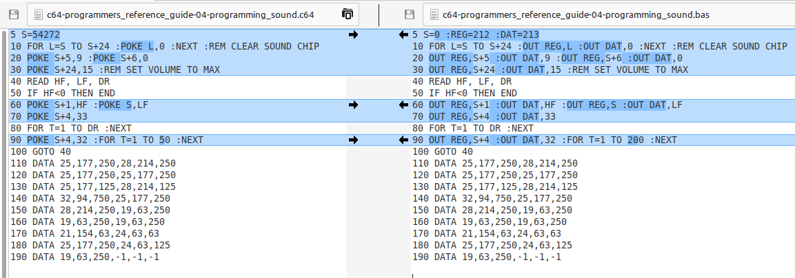
Line 5 sets the base address of the SID as 54272 (0xD400) and uses offsets later from this. For the RC2014, line 5 sets the base address to 0 and defines the REG and DATA addresses. After that, anywhere there is a POKE + offset, data on the Commodore, it becomes an OUT REG, offset : OUT DAT, data. The delay is increased on line 90 due to the RC2014 going much faster than a C64.
The example code is available on the RC2014 GitHub for you to copy & paste
Things work similarly in assembly code. This routine can be used to clear the registers at the start of your program.
            LD      L,$18
CLEAR:
            LD      A,L
            OUT     REG,A
            LD      A,0
            OUT     DAT,A
            DEC     L
            JP      NZ,CLEAR
Bill of materials
1 RC2014 SID-Ulator PCB
1 40 pin RA header
1 14 pin narrow DIL socket
1 16 pin narrow DIL socket
2 20 pin narrow DIL socket
1 28 pin wide DIL socket
1 74HCT86
1 74HCT138
1 74HCT688
1 74HCT374
3 100nf
1 3 pin header
1 jumper
2 1k6 resistor metal
1 3k resistor metal
2 47uf 25v electrolytic
1 3.5mm headphone socket
Sound samples
Writing about a sound module is all well and good, but a tune can paint a thousand words. Below are two versions of the same track played by the SID-Ulator. One set as a 6581(soldered jumper) and the other as an 8580 (unsoldered jumper)
Drivin’ was written by Shiela Dixon and used with permission