There are two types of test that are easy to do with a multimeter; continuity test and voltage test.
Continuity test
Set your multimeter to the continuity or beep setting. If you’re not familiar with how to do this, consult the documentation that came with it, or check out this Sparkfun guide. Power should not be applied for this part. All modules should be fitted to the backplane.
Start with one probe on pin 1 on the most left hand module. Put the other probe on pin 1 on the rest of the modules and confirm that they are connected. Repeat with pin 2 all the way through to pin 34
Put the probes on pin 1 and pin 2 of any module and confirm they are not connected. Repeat with pin 2 & 3, through to pin 35 & 36
Voltage test
Set your multimeter to measure DC Voltage. If you don’t have an auto-ranging meter, then set the range to 0-12v
Apply power to your RC2014. Measure the voltage across pin 17 (Gnd) and 18 (5v). It should be between 4.8v to 5.1v. Anything over this may have caused damage to the RC2014. Anything under won’t have damaged it, but is probably the cause for it not running.
With the black probe connected to ground, check the vcc pin of each IC. For the 14 pin packages, this is pin 14 (top right), for the 28 pin packages, this is pin 28 (top right), for the CPU this is pin 11 (halfway down left hand side), and for the 24 pin 68B50, this is pin 12 (bottom left). These should be 5v
On the CPU, pin 17 (NMI), 24 (Wait), 25 (BUSRQ), 26(Reset) should also be 5v.
Signal Tracer Circuit
On the RC2014-Z80 Google Group, Niels gave some info about building and testing a simple Signal Tracer circuit. The following is reproduced with his permission;
I don’t know what equipment you have but I’ll assume you have a multimeter that can read DC voltage.
So the first step is to check if the Z80 gets a clock. Unfortunately, very few multi-meters can read AC signals above 100kHz properly so you need to construct an AC probe to read the 7+ MHz clock signal. Luckily, this is easy and cheap to do.
You take two 100k resistors, a 10 nF capacitor, a 1N4148 diode and to construct the following signal tracer:
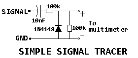
The component values are not critical at all. If you have 10k resistors, use 10k resistors. If you have a 100nF capacitor, use 100 nF.
Connect the ‘signal‘ end to the CLK signal on the bus of the RC2014 and the GND to the GND pin of the bus. Set your multimeter to DC volts. The meter will read more than 1 V if there is a changing signal on the CLK and much less (it should show something close to 0V) if there is a static signal (either 5V or 0V).
If there is a clock – good! If not, well, there’s your problem! :)
Now you can check whether the CPU is running a program. If it is, the address lines should be changing, so now connect the probe to a low-numbered address line, such as A2. If the meter shows 0V, the CPU is not fetching data and might be broken.
If the CPU is fetching data, connect the probe to the a couple of data lines. If you see changing signals, the ROM and/or RAM are probably working. If not, probe the chip select/enable pins on the ROM and RAM chips etc.
If the ROM/RAM board are working, probe the serial output pin on the 68B50. This is more difficult to do, because that pin will only change if the Z80 is accessing the serial port. You’ll have to keep resetting the RC2014 to get serial activity while looking at your multimeter.
These tests above will give you more information where the problem lies.
Of course, if you have an oscilloscope, use that to actually look at the signals instead of using the probe! :)