The RP2040 VGA Terminal is a simple terminal for the RC2014 to all the RC2014 to be used standalone. It connects to a regular VGA monitor and accepts a USB keyboard. It is based on the Pi Pico VGA Terminal with some enhancements.
The Hardware
This module uses an RP2040 micro controller from Raspberry Pi, and combines it with their reference design as found in their Hardware Design With RP2040 document to generate a VGA signal. This essentially uses resistors for each of the red, green and blue channels as a digital to analog converter. These 15 resistors are connected to the GPIO pins of the RP2040. With 5 bits per colour, 32768 colours are theoretically possible. 2 other GPIO pins are used for the H-Sync and V-Sync. The Micro SD support does stray from the reference design, though, as the reference design allows use of serial *or* SD, but not both. By swapping around pins for the SD card, both can be used.
The reference design also included 3 buttons connected to the least significant bit of each colour. While writing a scanline to the screen, pushing a button will have a barely noticeable effect on the picture. However, while the H-Sync or V-Sync signals are being generated, the GPIO pins for the switches can be set as input and the state can be read. This has already been useful in Pi Pico VGA Terminal for setting green-screen or amber-screen modes.
The Tx and Rx from the RC2014 connect through two jumpers. This allows either UART1 or UART2 on the RC2014 to be used. The GPIO of the RP2040 is not 5v tolerant, so the Tx from the RC2014 goes via a simple resistor voltage divider to bring it down to the 3v3 acceptable to the micro. The 3v3 Tx from the micro is above the threshold needed that it can be heard by the SIO/2 or MC68B50 of the RC2014. Note that if you wish to use this for VGA output only, and not USB keyboard input, the Tx jumper should be removed.
The module is powered from the RC2014 bus. A Schottky diode on the Vsys pin of the RP2040 allows it to safely be connected to both a live RC2014 and powered from a USB cable too.
Additional hardware not included on the Pi Pico VGA Terminal
A micro SD card socket is attached to some of the original spare GPIO lines, and hopefully this will be useful for storing config files, font bitmaps, sprite data, macros or other enhancements.
A USB Type C socket is fitted for uploading of firmware.
An I/O expander is included which provides 4 additional I/O lines. One of these drives a piezo active buzzer allows for the ASCII BELL signal to make a beeping noise. The other controls the power to a full size USB socket. This means that unplugging/replugging of some keyboards is no longer needed as the PicoTerm software can do this automatically. The full size USB Type A socket allows a regular keyboard to be plugged in without a USB-OTG adapter.
The original Pi Pico VGA Module had a few spare GPIO pins which were bought out to a header. Whilst these are mostly used up with the additional hardware, the same header has been used on the board, along with some additional GPIO pins from the RP2040 that are not exposed on the Pi Pico, and the additional pins from the GPIO expander.
3 diagnostic LEDs indicate incoming power, outgoing power to USB keyboard and GPIO25 for keyboard not detected.
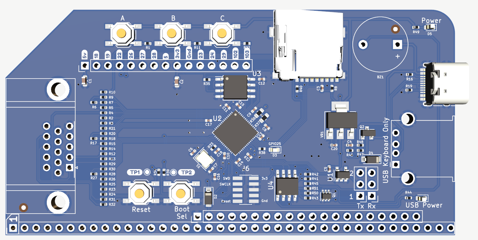
All 87 surface mount components are assembled, tested and programmed. Only the large through-hole connectors need to be fitted.
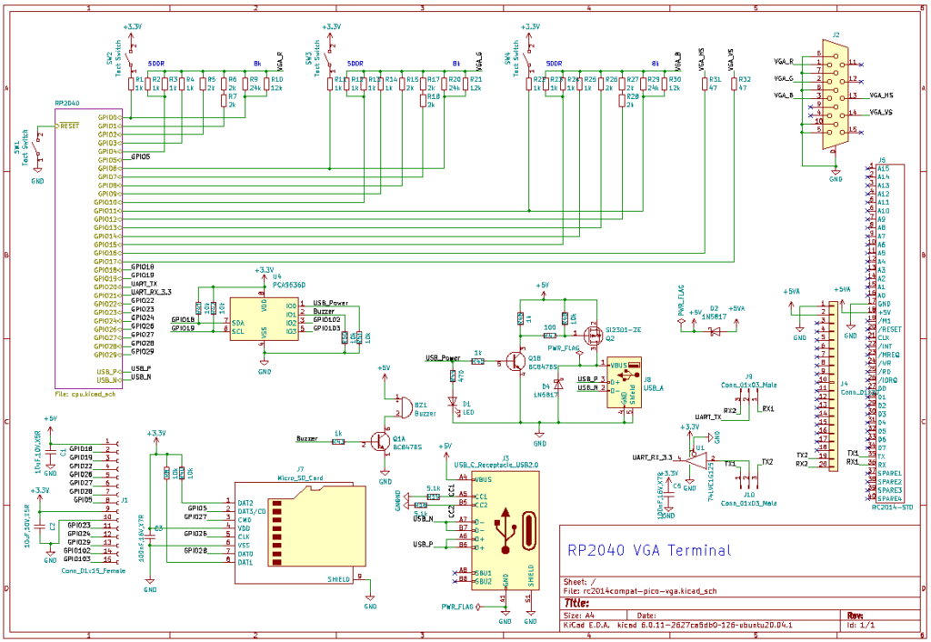
Click for link to pdf schematic
Software
PicoTerm was originally written for the Pi Pico VGA Terminal, and will run perfectly well on this hardware too. It is being developed to include enhancements for the additional hardware that this module supports.
PicoTerm offers the following features:
- Super easy firmware upgrade (see firmware upgrading doc)
- VGA output with several color profiles (green, amber, yellow, …)
- 80 columns over 30 lines (40 columns color version also available)
- USB Keyboard support (via OTG cable)
- Multiple keyboard layout (US,UK,BE,FR,DE,…)
- VT100 style escape codes terminal (listed below).
- ASCII 7 bits mode (8th bit used for reverse video character like CP/M does).
- ANSI 8 bits mode for semi-graphical charset. Activable with ESC sequence.
- Multiple ANSI/advanced graphical charset availables
- NupetScii : charset merging several retro-computer character sets (C64, MSX, MSDOS). Great for ASCII art, interface design, map drawing, drawing ressource with Playscii.
- CP437 : IBM MS-DOS codepage for english computer.
- Up to 16 charsets possible
- Multiple Font-Face supported (see multiple font-Face support )
- Ubuntu Mono8 (from Pico-SDK)
- Olivetti Thin (from int10h.org)
- PicoTerm connector : expansion port
- SD card reader [under construction]
- Active Buzzer
- Delayed USB power-up
- Poor man debug output
- Various helper screen (SHIFT+CTRL+)
- SHIFT+CTRL+H : Help screen (with all shortcut).
- SHIFT+CTRL+M : Configuration screen with storage into flash.
Programming Firmware
The RP2040 uses a UF2 bootloader to appear as a mass storage device so that new firmware can be uploaded to it. To do this, connect a USB Type C lead between the RP2040 VGA Terminal and your PC/Mac/Laptop/Raspberry Pi/Android Phone. Then push the BOOTSEL button on the board. Whilst holding this down, push and release the Reset button next to it. (Trust me. This is easier to to than to put in to words!). The RP2040 will then show up as a drive on your computer. Simply drag and drop the UF2 firmware on to this drive. The RP2040 will automatically reboot and disconnect once this is complete.


Bill Of Materials
- 1 RP2040 VGA Terminal PCB with SMD components
- 1 RA VGA Socket
- 2 3 pin Header
- 2 Jumper
- 1 Active Piezo Buzzer
- 1 USB Type A Socket
- 1 RA 40 pin header *or* 1 RA 2×40 pin header