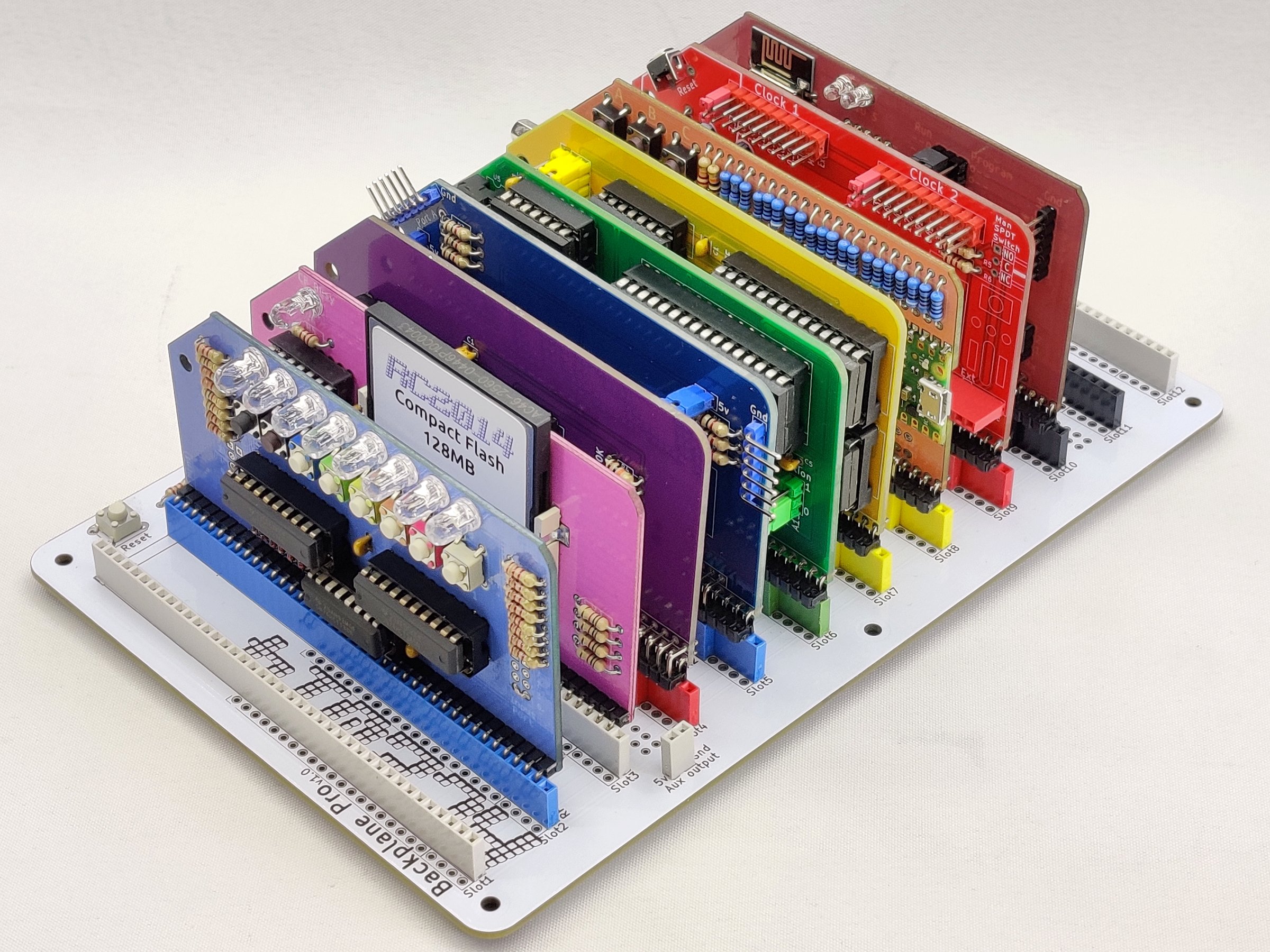
The RC2014 Pro Pride and the RC2014 Zed Pro Pride are limited edition kits based on the RC2014 Pro and RC2014 Zed Pro respectively. The major difference is that they use PCBs and various components that represent the Pride Flag. They also include a Pi Pico VGA Module, a Digital I/O Module, an ESP8266 Wifi Module, and in the case of the RC2014 Zed Pro Pride, a DS1302 RTC Module is also included. They will be available on z80kits.com during June 2023 and will raise money for Trans and LGBTQI charities
All modules are functionally equivalent to their non-Pride modules, and with the exception of resistors for the LEDs, are electrically equivalent too. So for this page, I won’t go in to the details covered elsewhere, but will focus on the parts that make them different and what you need to be aware of when assembling the kit. Mostly that means a list of coloured parts to use on each module – however, these are merely suggestions, and you’re a grown up, so feel free to put things in any order with whatever colour components you wish.
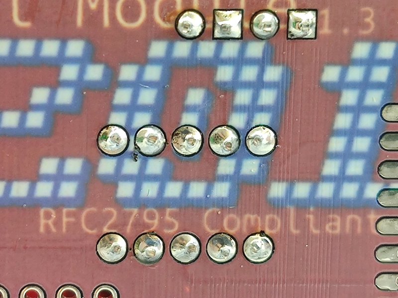
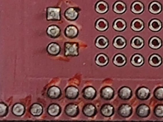
One important thing to note is that to get the PCBs in the right colours for this kit, 4 of them (Digital I/O, Compact Flash, Pi Pico VGA and ESP Wifi) were printed using a dye sublimation process. I have written a blog post about that journey and what is involved with that. However, the key takeaway point is that the dye will vaporise at temperatures above 180’C. That’s below the temperature of your soldering iron! So for these boards you will have to be a little bit more careful to only apply your soldering iron to the component leads and to not touch the dyed parts of the board.
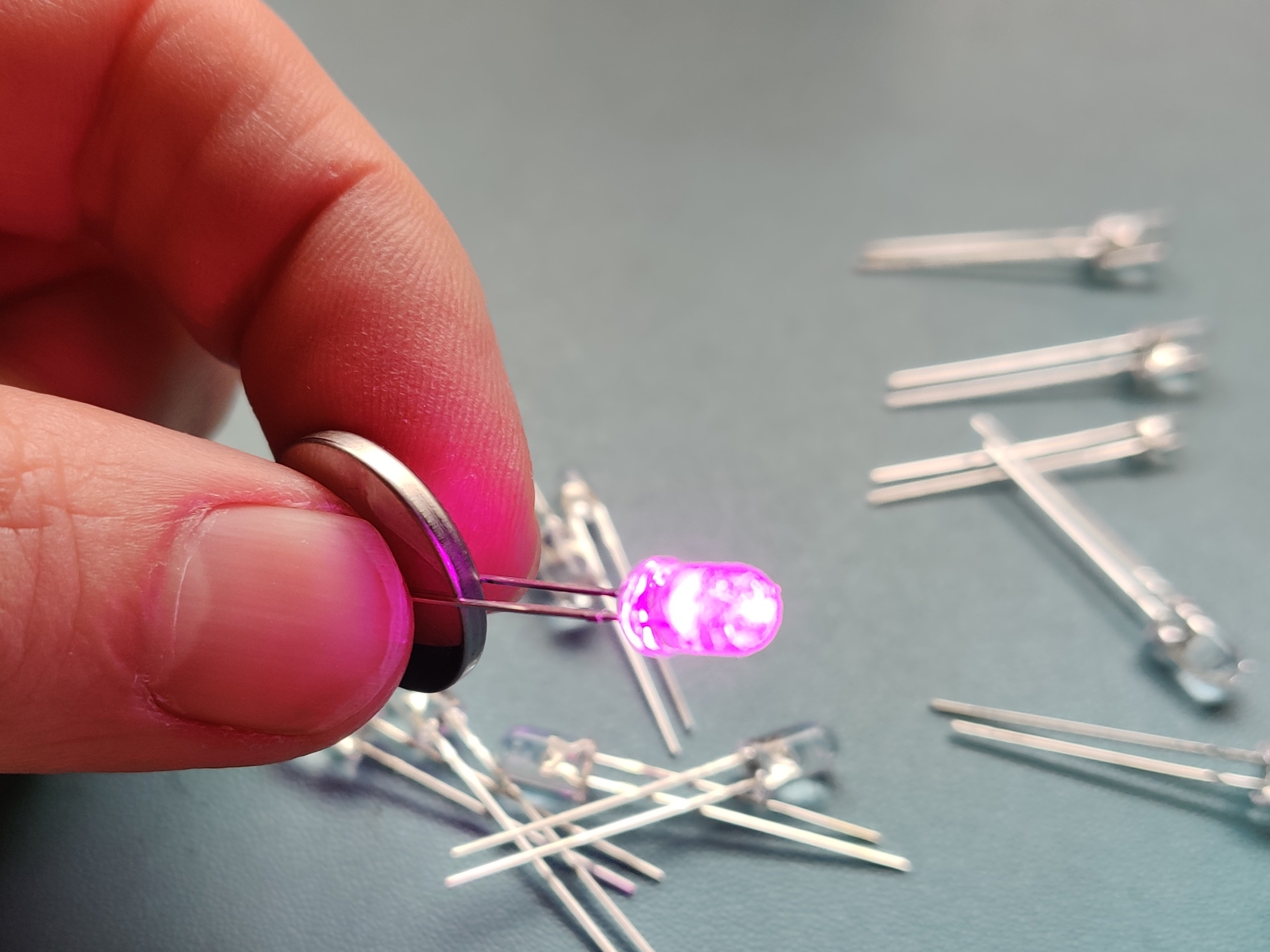
The other thing that you will notice when you get your kit is that all the LEDs have a clear lens despite emitting different colour light. But how can you tell which colour each LED is? Well, each kit includes an LED tester (aka CR2032 coin cell battery!). Simply hold the LED legs across the battery and you can tell what colour it is. Most LEDs are 5mm, although there are two 3mm LEDs which need to be used on the ESP8266 Wifi Module.
There is a full Bill Of Materials for the RC2014 Pro Pride and the RC2014 Zed Pro Pride which is broken down by component and by module, so you can organise your build by component or module whichever suits you best.
Digital I/O Module
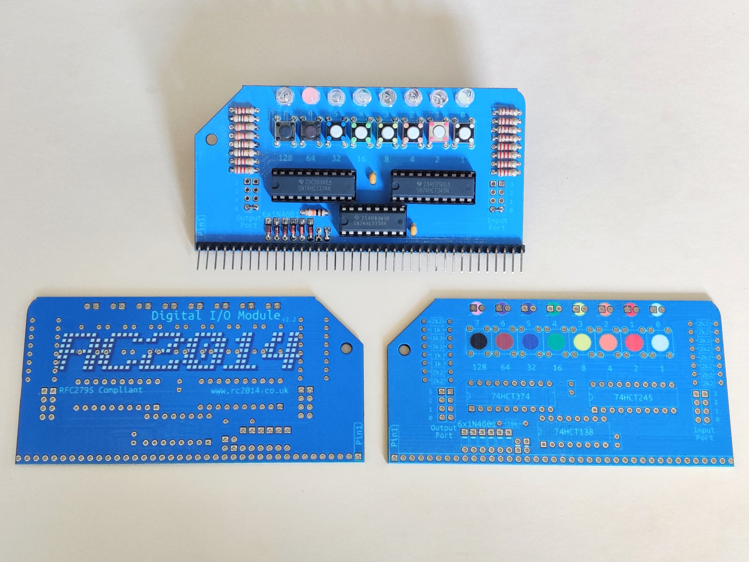
This is a dye sublimated module, so take extra care when soldering. The LED colours are depicted on the PCB, which from left to right are violet, pink, blue, green, yellow, orange, red and white. Similarly the switch colours are depicted on the PCB too. From left to right black, black with brown button, blue, green, yellow, orange, red and white. To match the relative LED brightnesses, the resistors are different to the standard Digital I/O module, and from top to bottom are; 2k2, 1k, 3k3, 3k3, 1k, 1k, 2k2, 2k2. See also Digital I/O Module
Compact Flash Module
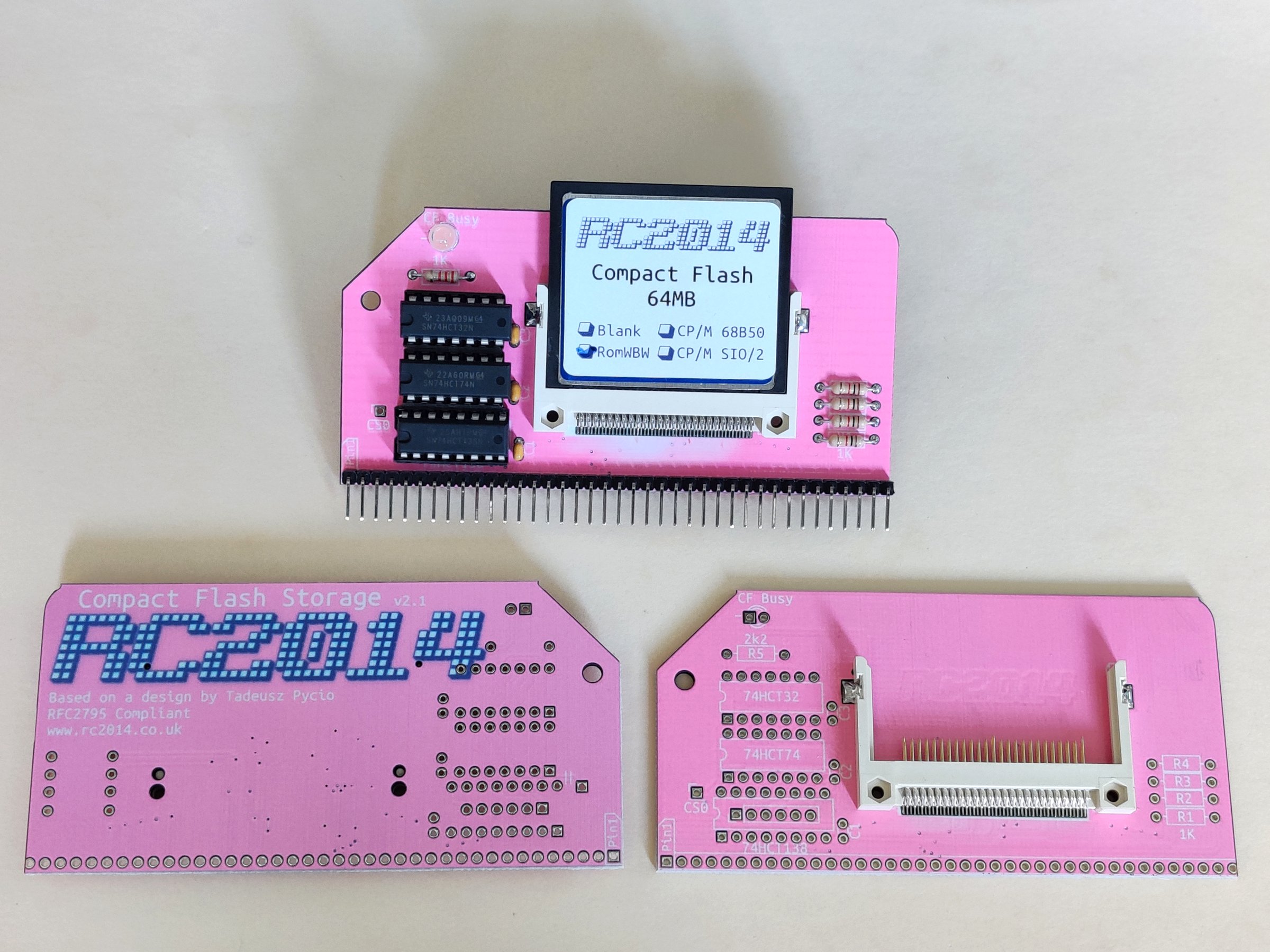
This is another dye sublimated board, so take care with the soldering. There may be a bit of fading around the compact flash connector which is caused when the hot air reflow is used for the surface mount soldering. Sorry about that. Use the pink LED for this module, and a 2k2 resistor just below it. The RC2014 Pro Pride then it comes with a 128mb CF card with CP/M 2.2 and the RC2014 Zed Pro Pride comes with a 64mb card with RomWBW Combi Image. Otherwise it is the same as the Compact Flash Module v2
Z80 CPU
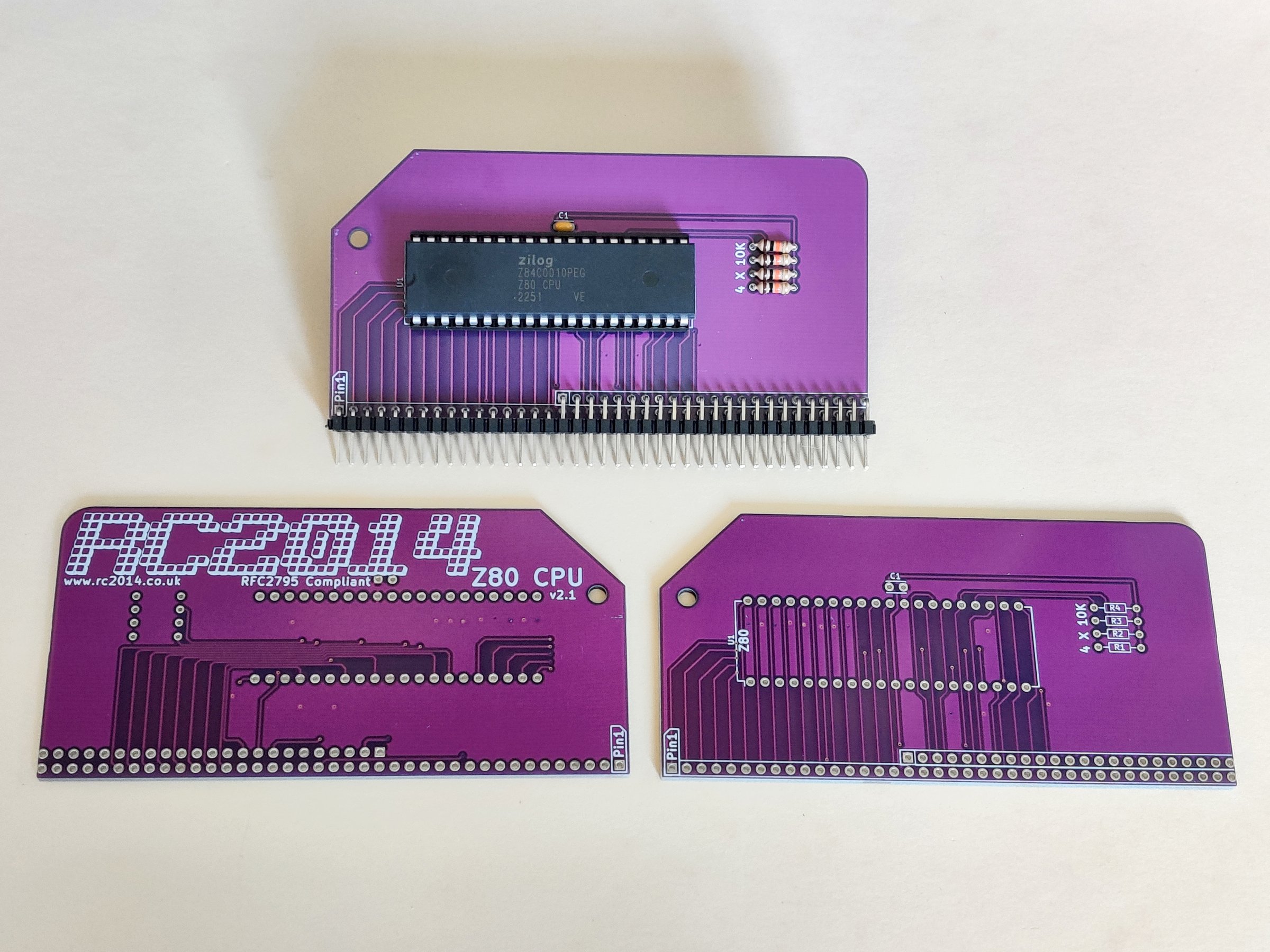
Aside from the colour of the PCB, this is exactly the same as the regular Z80 CPU Module
SIO/2 Dual Serial Module
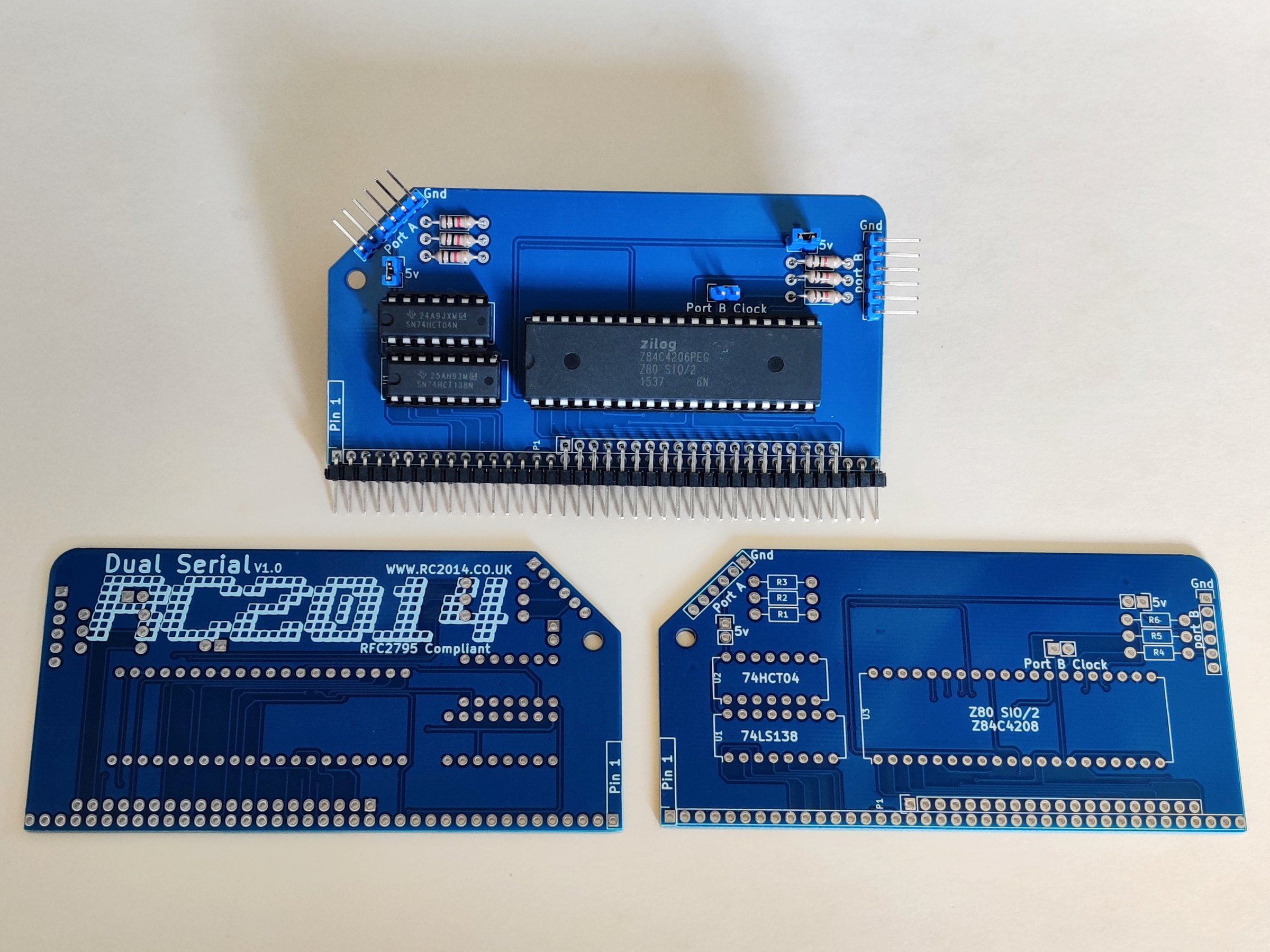
Use the blue 2 pin headers and jumpers on this, and the blue 6 pin right angle headers. Otherwise it is identical to a regular Dual Serial Module
Pageable ROM (RC2014 Pro Pride model)
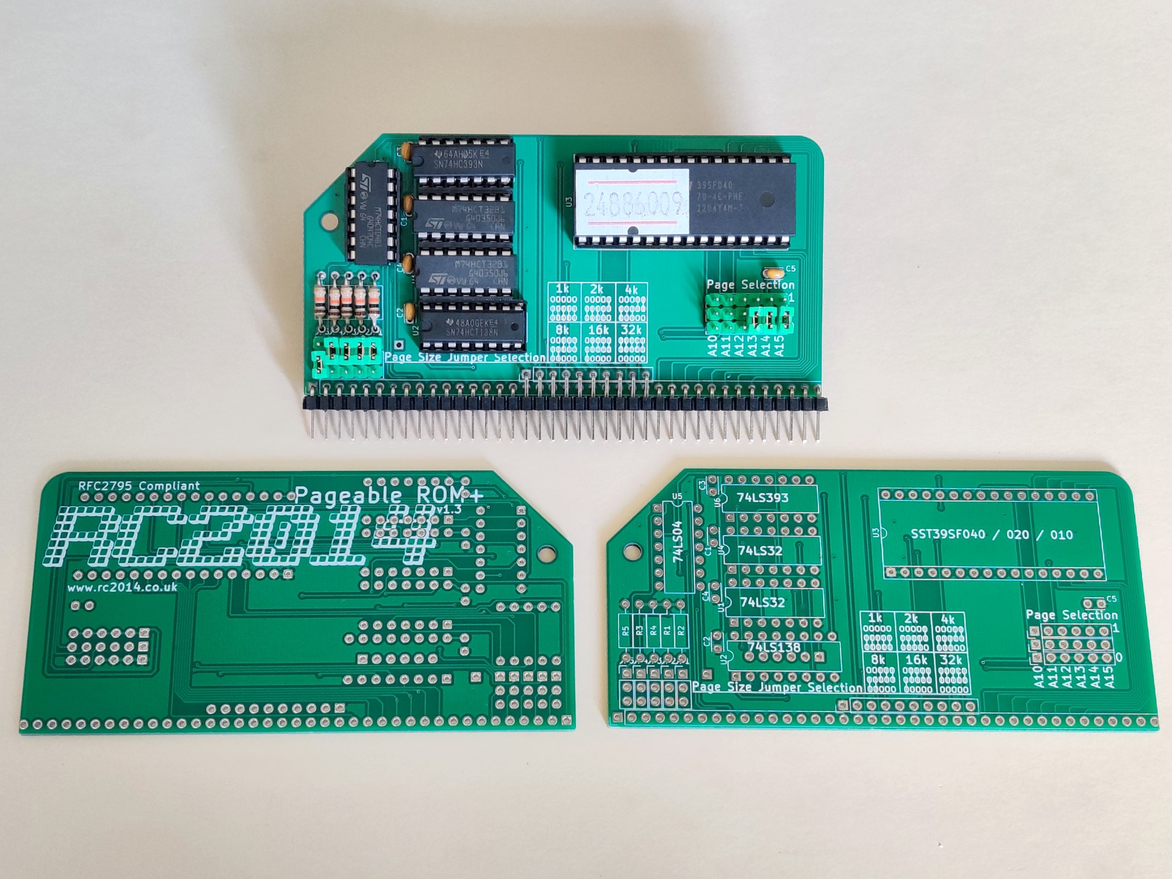
Use green header pins and jumpers here. This module is virtually identical to the standard Pageable ROM Module, although this one uses a 32 pin 39SF010 ROM. The jumper configuration is the same, and if you use the settings shown above then it will boot to BASIC. See the RC2014 Pro Jumper Settings for other configurations.
512k ROM 512k RAM Module (RC2014 Zed Pro Pride model)
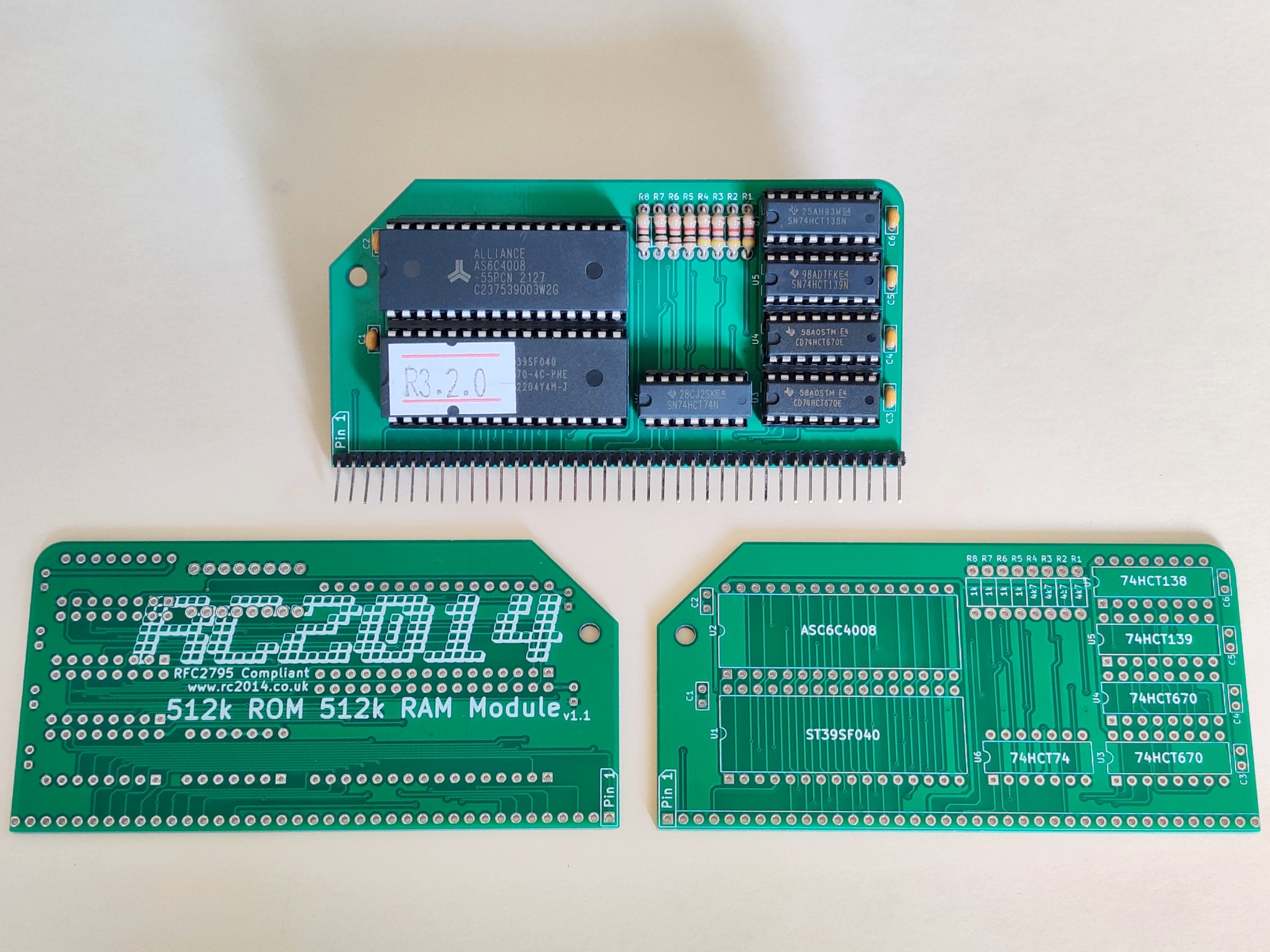
Aside from the PCB colour, this is identical to the regular 512k ROM 512k RAM Module
64k RAM Module (RC2014 Pro Pride model)
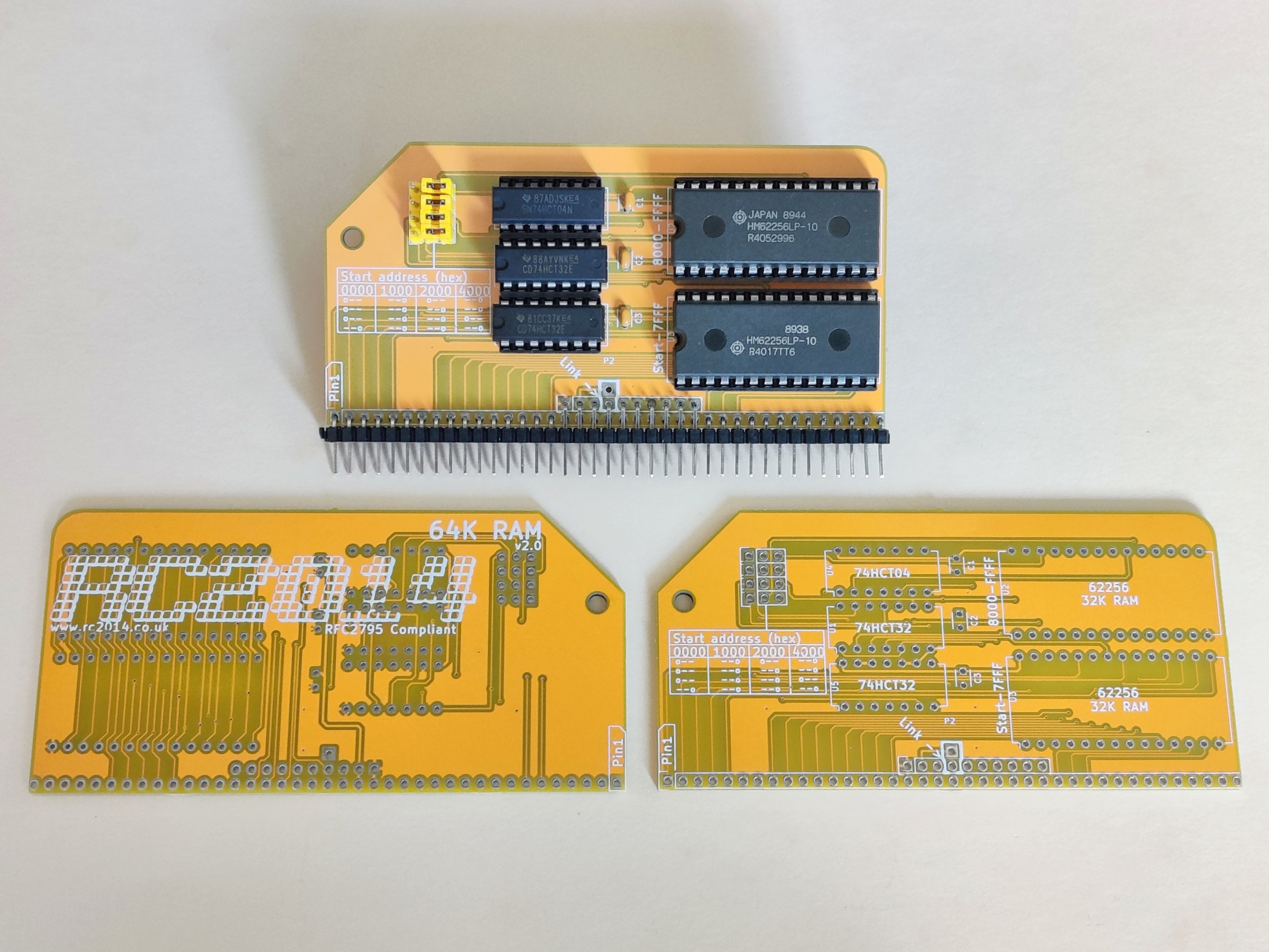
Use the yellow pin headers and jumpers on this board. All jumpers should be set to the right two pins and the “link” on the silkscreen should be ignored. See the 64k RAM Module for details, or the RC2014 Pro Jumper Settings as mentioned above.
DS1302 Real Time Clock Module (RC2014 Zed Pro Pride model)
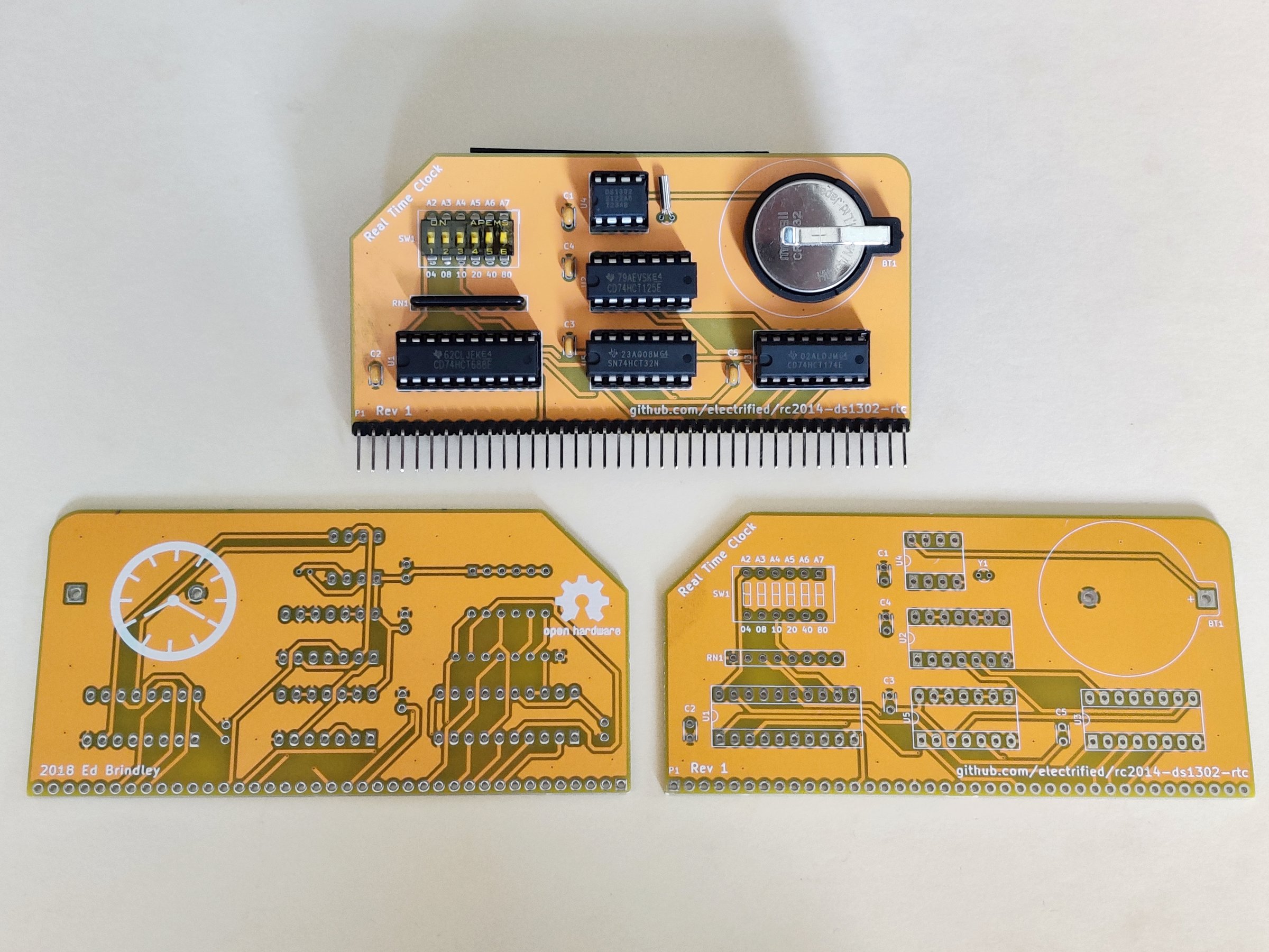
Aside from the PCB colour, this is a standard module. The address C0 should be set on the DIP switch, which is positions 5 and 6 both ON. DS1302 Real Time Clock Module
Pi Pico VGA Terminal
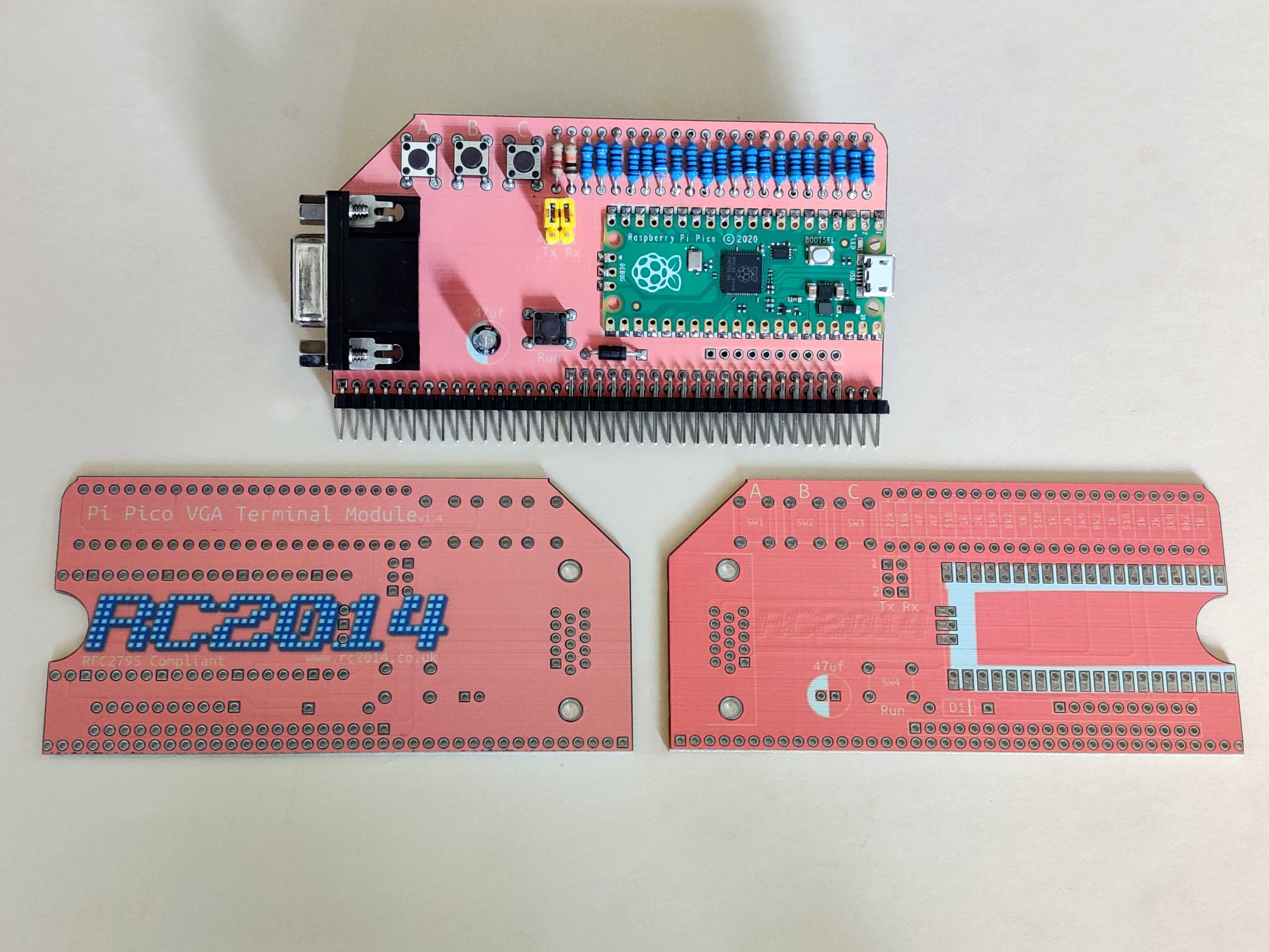
This is another dye sublimated board, so care must be taken when soldering, particularly around the Pi Pico. Orange jumpers and header pins are not available, so you will need to use yellow. The black/brown tactile switches are used too. Note that if you are using the Wifi module or FTDI adapter for serial input then the right jumper must be removed. For full info, see Pi Pico VGA Terminal and also Pi Pico Soldering Tips
Dual Clock Module
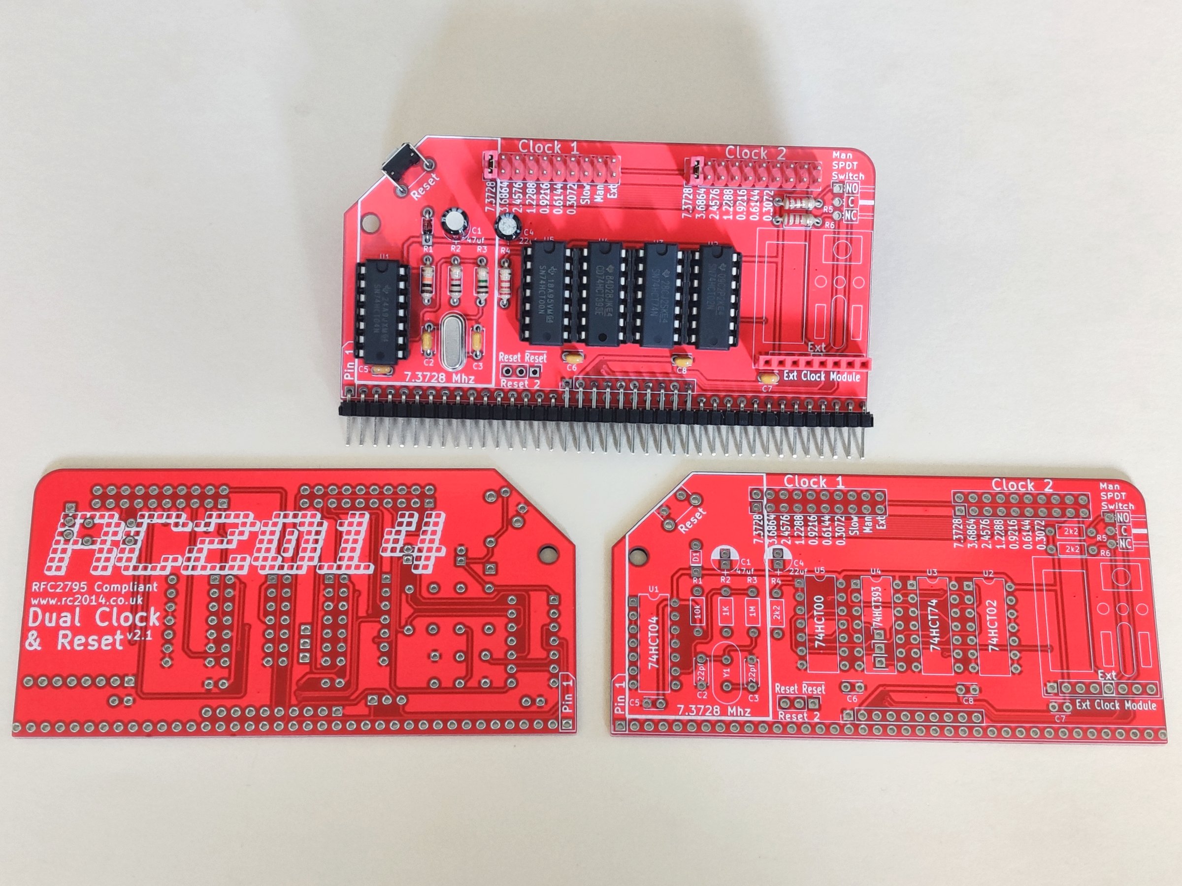
This module uses the white square right angle tactile switch, the 2×10 red pin headers, 2 red jumpers and the 8 pin SIL socket. It is otherwise the same as the Dual Clock Module
ESP8266 Wifi Module
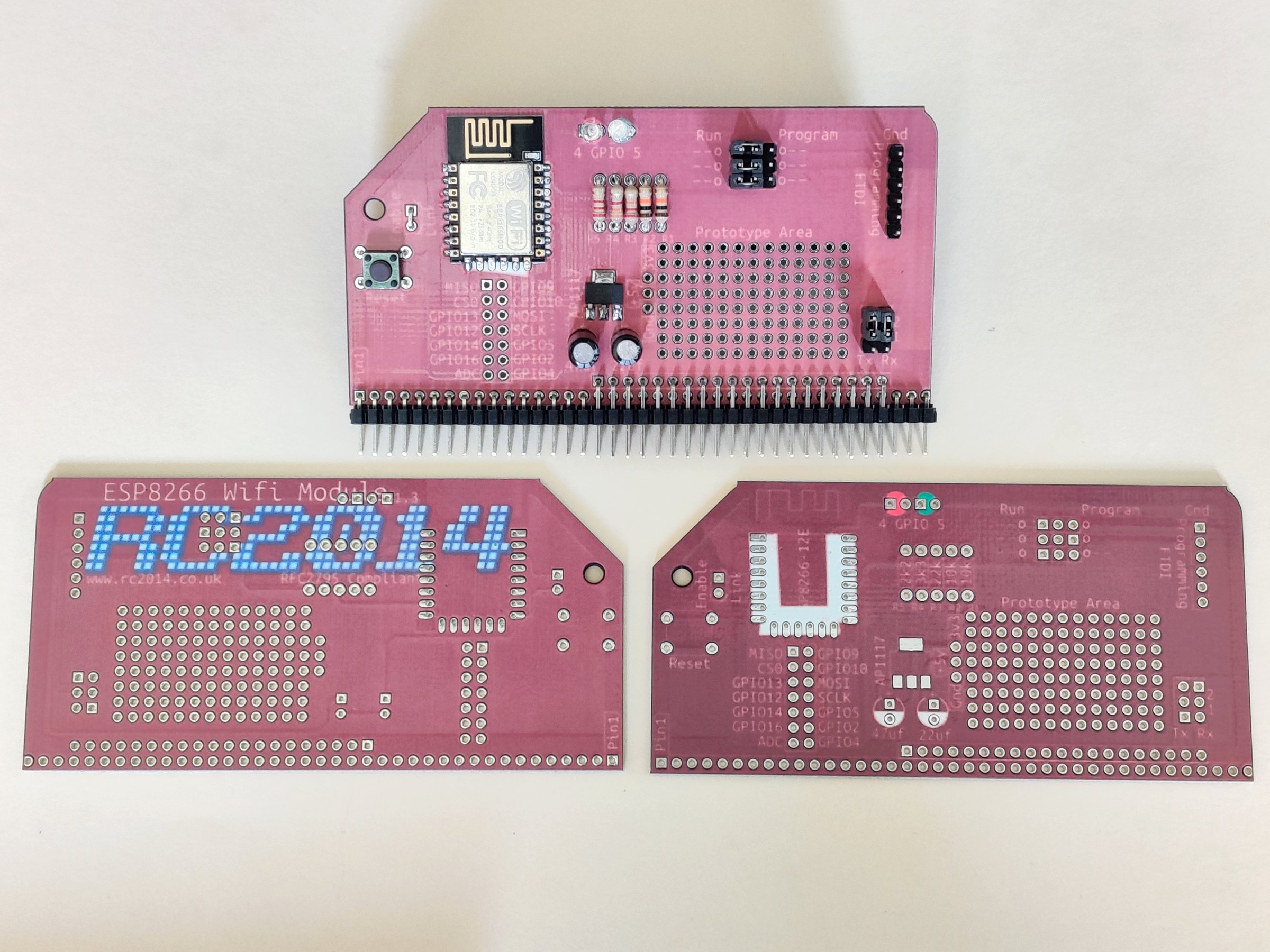
This is also a dye sublimated board, so take care. Use the red and green 3mm LEDs here as indicated. From left to right the resistors are 2k2, 3k3, 22k, 10k, 10k. Black header pins and jumpers should be used, and a black/brown tactile switch. Note that if you are using the VGA module or FTDI adapter for serial input then the right jumper must be removed. Refer to ESP8266 Wifi if you need further information
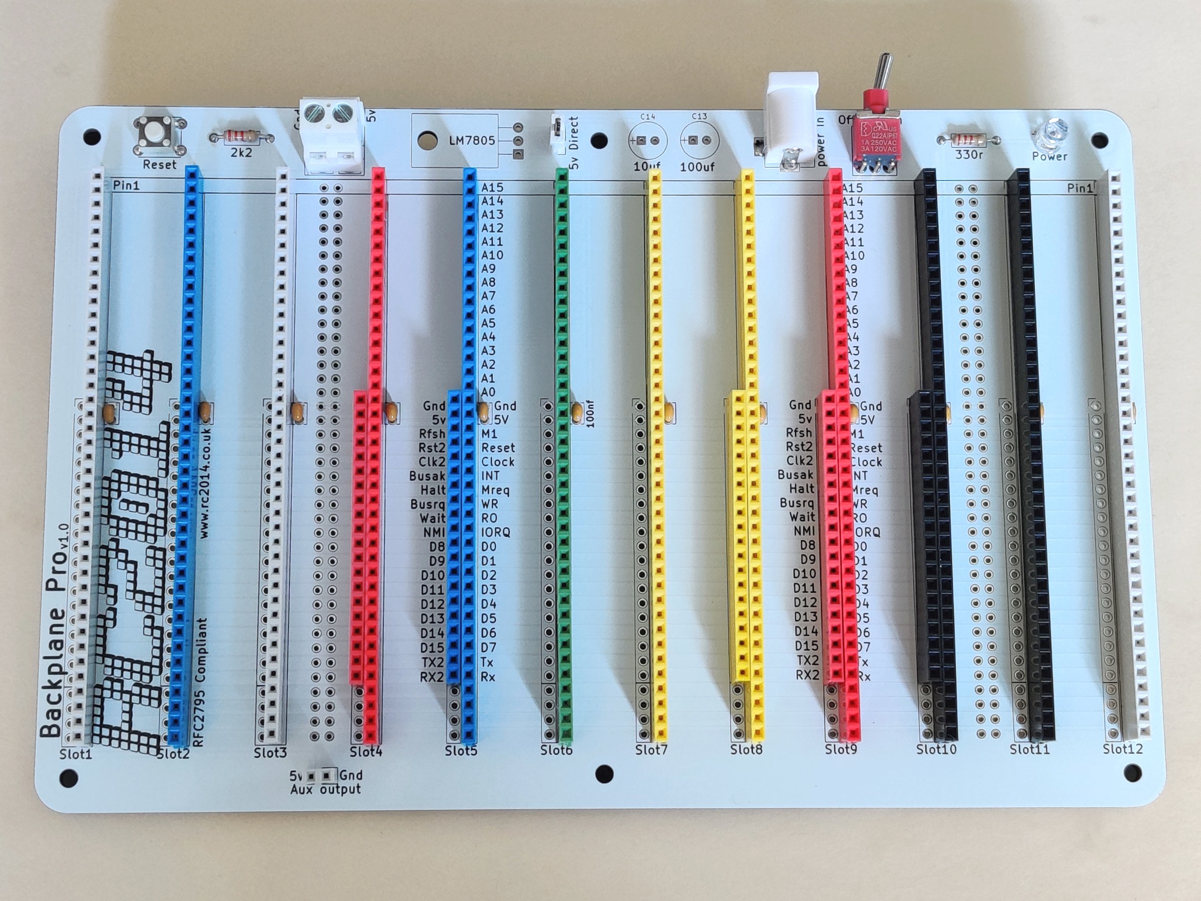
Backplane (RC2014 Pro Pride model)
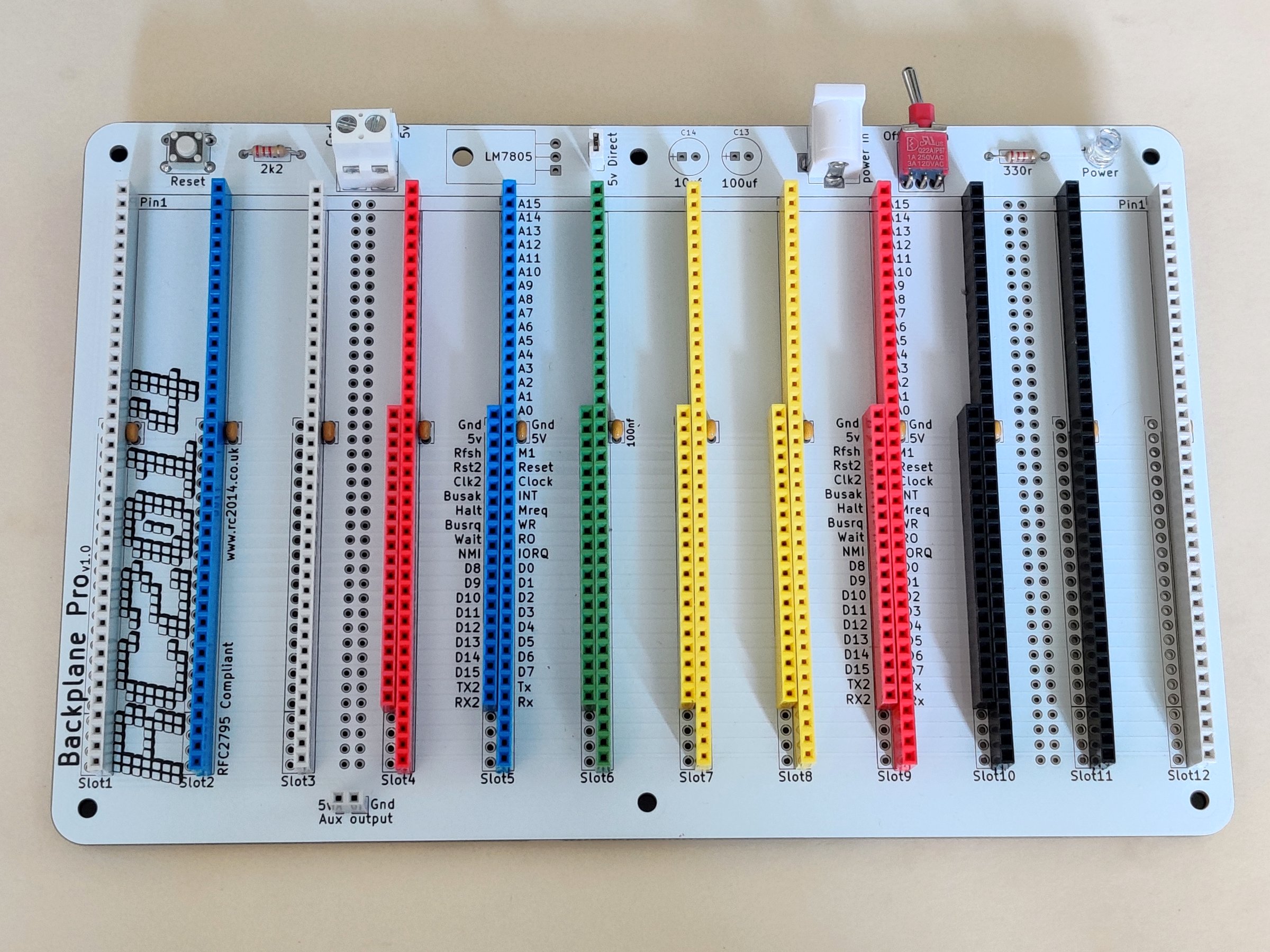
Use white tactile switch, white screw terminal, white 2 pin header, white jumper, white barrel socket, white LED and white 2 pin socket on this board. Use a 2k2 resistor for both the reset switch and LED despite what the silkscreen says. From left to right the sockets are 40-white, 40 blue, 40 white, 20 red, 40 red, 20 blue, 40 blue, 20 green, 40 green, 20 yellow, 40 yellow, 20 yellow, 40 yellow, 20 red, 40 red, 20 black, 40 black, 40 black, 40 white. (This is slightly different to the RC2014 Zed Pro Pride model so ensure you are using the photo above, not the photo below!).
Backplane (RC2014 Zed Pro Pride Model)
Use white tactile switch, white screw terminal, white 2 pin header, white jumper, white barrel socket, white LED and white 2 pin socket on this board. Use a 2k2 resistor for both the reset switch and LED despite what the silkscreen says. From left to right the sockets are 40-white, 40 blue, 40 white, 20 red, 40 red, 20 blue, 40 blue, 40 green, 40 yellow, 20 yellow, 40 yellow, 20 red, 40 red, 20 black, 40 black, 40 black, 40 white. (This is slightly different to the RC2014 Pro Pride model so ensure you are using the photo above, not the photo above that!).
White Socket Backplane
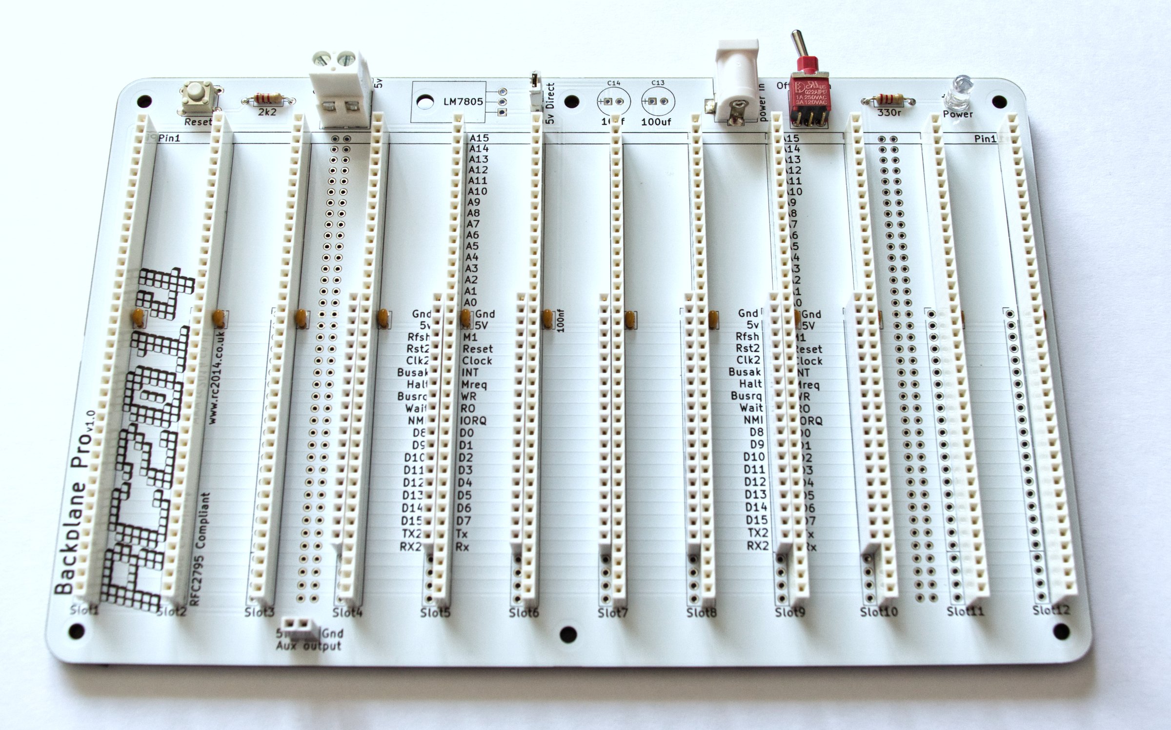
If you got your kit with all white sockets, then the instructions are the same as above – except use white sockets instead of blue, red, green, yellow and black :-)
The RC2014 Pro Pride has 7 20×1 SIL sockets, and these go in slots 4, 5, 6, 7, 8, 9 and 10.
The RC2014 Zed Pro Pride has 5 20×1 SIL sockets, and these go in slots 4, 5, 8, 9 and 10
First Bootup
When assembling your kit, I suggest starting with the bare minimum of modules and testing those work before moving on to the expansion modules. This will be the Backplane, Z80 CPU, SIO/2 Serial, Dual Clock, and either the Pageable ROM + 64k RAM or the 512k ROM 512k RAM Module depending if you have the RC2014 Pro or RC2014 Zed Pro kits.
Give everything a good visual inspection, then plug the modules in, ensuring pin 1 on the module lines up with pin 1 on the backplane. Use Port A on the SIO/2 module and connect to a terminal running at 115,200 baud 8-n-1. When you see either the Microsoft BASIC prompt or the RomWBW initialisation screen then you’re good to go! Time to crack on with the rest of the modules!