Note – This module has been retired. Click here for updated Digital I/O Module
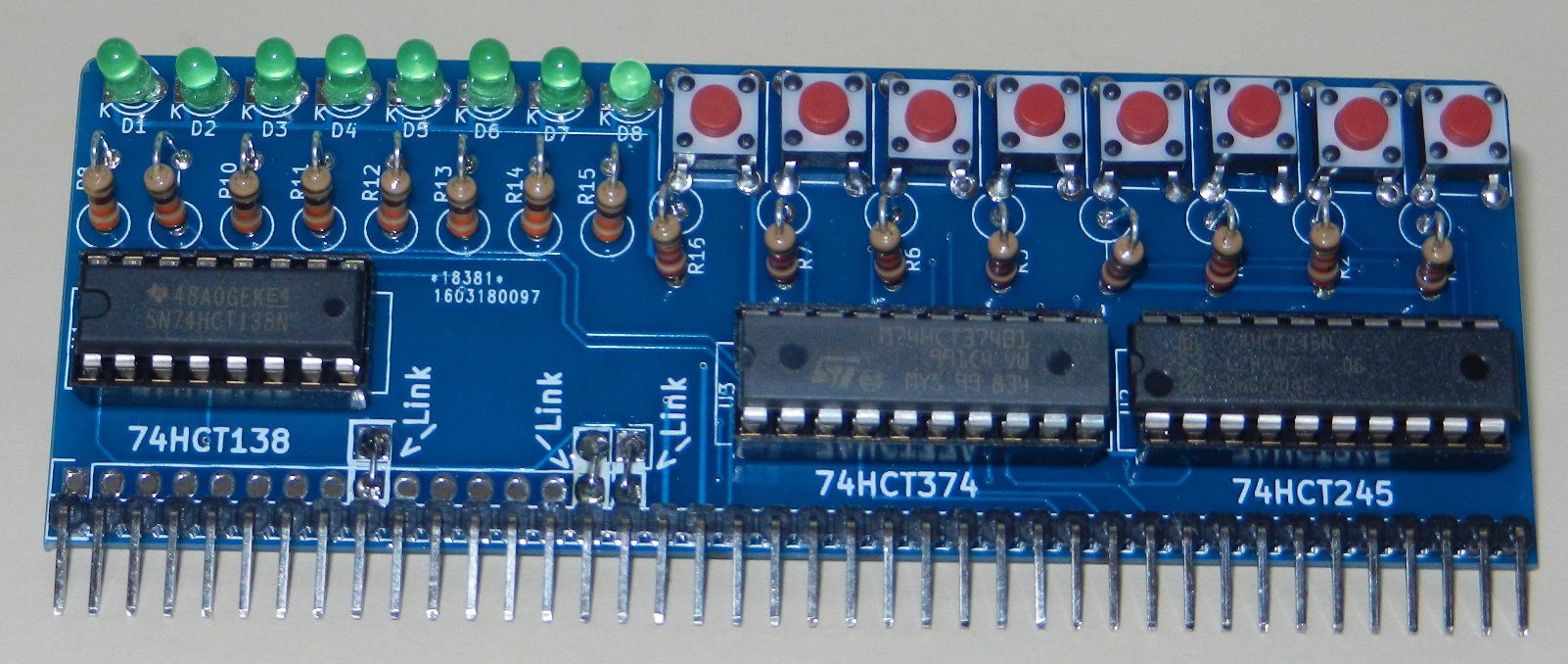
The digital I/O module provides 8 lines of digital input and 8 lines of digital output via pushbuttons and LEDs. Values between 0 – 255 are read from or written to port 0, where the digital representation of that number is expressed with a 1 to represent a button being pushed or a LED being on
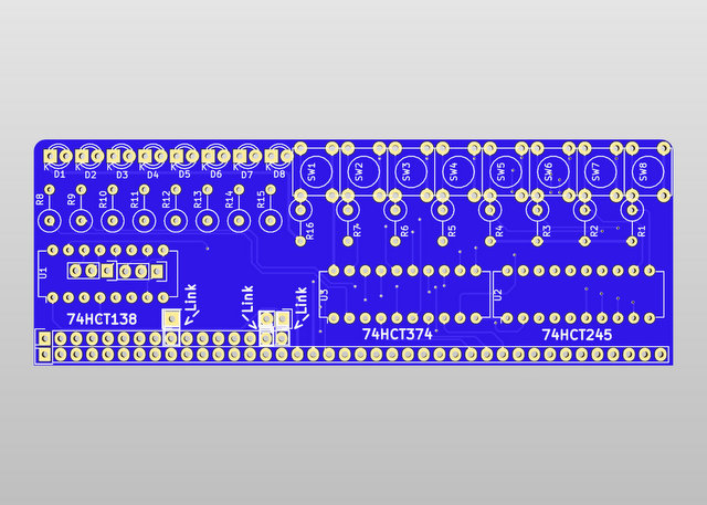
Address lines A0, A1 and !A7 along with M1, IOReq and !WR are used to select the multiplexer 74LS138. This is capable of 8 lines of switching, although for this board, only 2 (1 input and 1 output) are used – the other 6 are broken out to pads for further expansion if required.
The address selection pins from the 74LS138 need links to be soldered. It is assumed that A0, A1 and A7 will be used, however, if this clashes with other devices, the other address lines are broken out to be used as required.
A 74LS245 transceiver is used to read (!Dir connected to ground) 8 spst tactile switches. These switches are pulled low by 2k2 resistors R1-R7 & R16* and when the Chip Enable pin is pulled high, the value of these 8 switches are put on the databus
Similarly, a 74LS374 flip-flop will read the databus when the Chip Enable pin is pulled high, and output the values on 8 LEDs via 330 ohm resistors. This value is latched, so when the CE pin is no longer high, the output stays to what it was last set to.
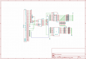
Click image below for schematic in PDF format
In BASIC the port can be read with the INP(0) command which will return a number from 0 to 255, and written to with OUT 0,x where x is the number to output from 0 to 255
In assembly language, the mnemonics in a , (0) and out (0) , a do the same function
Example BASIC program where the buttons are read and their value displayed on the lights
10 OUT 0,INP(0)
20 GOTO 10
Simple cylon scanner program
10 FOR F=0 TO 7
20 OUT 0,2^F
30 GOSUB 100
40 NEXT F
50 FOR F=7 TO 0 STEP -1
60 OUT 0,2^F
70 GOSUB 100
80 NEXT F
90 GOTO 10
100 FOR X = 1 TO 150 : NEXT X : RETURN
Buy one here
Bill of Materials
- RC2014 Digital I/O PCB
- 40 pin header
- 20 pin narrow DIL socket x 2
- 16 pin narrow DIL socket
- 74HCT245
- 74HCT374
- 74HCT138
- 3mm Green LED x 8
- Tactile Switch x 8
- 2k2 resistor x8
- 330R resistor x 8
* Note to self – When Kicad annotates a schematic, it uses the Y position before the X position, which in this case results in the discontiguous numbering of the input resistors