The LCD Driver Module allows you to connect a variety of HD44780 based LCD character screens to the RC2014 and easily program them from BASIC or Z80 assembly code – Or whatever is your preferred programming language.

This module uses Port 0xDA/DB for the register and data addresses, which fits in nicely with the Why-Emulator and SID-Ulator modules. Alternative addresses of 0xAA/AB, 0x5A/5B and 0x2A/2B are also easily configured. 3 connectors are available for either a 2×8, 2×16 or 4×20 screen, although other screens may be fitted
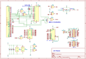
Click image to open PDF schematic

Assembly
Assembly is pretty straightforward. Similar to other RC2014 modules, start with the lowest profile components and work upwards. Note the orientation of the chips sockets and that you use the correct ICs in each one.
- If you are using a 2×8 character LCD screen, fit the 2×7 pin socket on the left hand side.
- If you are using a 2×16 character LCD screen, fit the 1×16 pin socket on the top of the module
- If you are using a 4×20 character LCD screen, or any other size you will need the 2×10 right angle pins fitting on the right side of the module. Note that this needs to be raised slightly off of the PCB, so it is easiest to fit the IDC extension cable to the pins before soldering the pins so that you have the right spacing. You will also need to solder a link across the BL/-VE jumpers for the backlight . The PDF schematic for the 2×10 to 1×16 adapter for the 4×20 screen can be found here
Hardware
The addressing is handled by an ’02, ’86 and a ‘688. Firstly, the ’86 XORs A6 with A5 and also A6 with A4. This means that the 010 and 101 pattern formed in the port address DA/DB and AA/AB can be identified. (It will also identify ports 5A/5Band 2A/2A too. More on that later). An ‘866 comparator is then used to look at A7, A3, A2, A1, M1 and IORQ. If these match the levels on the other side of the ‘866 then the output is NORed with either A5 or A6, where either A5 or A6 is selected by a jumper for DA/DB addressing or AA/AB addressing, to produce an enable signal for the LCD display.
A0 goes via one of the XOR gates on the ’86 that is used as a buffer and is supplied to the LCD display as the RS signal. When A0 is low, the registers are being addressed, and when A0 is high, data is being addressed.
A big Thank You goes to Mike Sutton for the Read/Write part of this circuit. The LCD screen needs a R/!W signal (Read or Not-Write). Using the !WR pin on the Z80 would seem like the obvious thing here, but sadly it does not work. However, inverting the !RD does. So, putting the !RD signal through another spare XOR gate configured as an inverter gives a !!RD, or simply RD, which allows registers and data from the screen to be read. You can read a more detailed explanation of this on Mikes blog https://bread80.com/2020/07/01/connecting-an-lcd-to-a-z80-with-two-glue-chips/
A ‘245 is used as a buffer for the data lines with the !RD signal used to set the direction and an inverted Enable signal used to enable the chip. This allows a screen to be connected via a ribbon cable whist keeping the Z80 data bus integrity intact.
Two 10k potentiometers are used as voltage dividers. One for the contrast, and one for the backlight. The backlight signal also has a 100 ohm resistor in series to limit current.
The power, control, contrast, backlight and data signals are routed to 3 connectors (The 0208 screens do not have backlight adjustment). In addition, a couple of other signals, such as the Reset and !RD are also sent to the 2×10 connector. These signals should allow a 24064 screen to be used, but at time of writing, this is untested.
Using the 2×10 connector via a ribbon cable for a remote display with a 1×16 header to be used means the matching 2×10 to 1×16 adapter PCB must be used. The 3 pin header next to the 2×10 header needs a link soldering across the central BL pin and the -VE pin. (For a 24064 screen, the outer pins of VCC and Ground should be connected). Note that on the v1.1 revision of the PCB the silkscreen indiacating that BL and VCC should be linked is wrong. From v1.2 onwards this is corrected to show BL and -VE need to be linked for an external display.
Port 2A/2B or 5A/5B Hack
Port DA/DB should be fine for most people and not clash with anything. In case it does, port AA/AB can be used by setting the jumper at the top of the module. In the very rare circumstance that you have other modules clashing that cannot be changed, there is a cuttable link under the ‘688. If this link is cut and the other two pads are joined then the module will respond to either port 2A/2Bor 5A/5B
Software
The datasheet for the HD44780 is really useful for getting the most out of these character displays, however, simply writing text to them is very straightforward. This example BASIC program sets up the screen, asks for input and displays it on the screen.
10 R=218    : REM 0xDA - Register
20 D=219    : REM 0xDB - Data
30 OUT R,56 : REM 0011 1000 - Function 8 bit, 2 lines, 5x8 dot font
40 OUT R,14 : REM 0000 1110 - Display on, cursor on, no blink
50 OUT R,1  : REM 0000 0001 - Clear display
60 INPUT "Text to display";T$
70 FOR A=1 TO LEN(T$)
80 PRINT MID$(T$,A,1);
90 OUT D,ASC (MID$(T$,A,1))
100 NEXT A
Note that some actions on the screen take some time to execute, such as clearing the screen. While this is being carried out further instructions are ignored. This is not a problem in BASIC, as even the slowest actions complete well before the next instruction can be written. However, if programming in assembly, then you should read the registers and only send further commands once the Busy register is clear. Again, Mike Suttons blog explains this very well and has some example code too https://bread80.com/2020/07/01/connecting-an-lcd-to-a-z80-with-two-glue-chips/
Bill of Materials
2×8 LCD Driver Module
1 RC2014 LCD PCB
1 40 pin header
1 74HCT688
1 74HCT86
1 74HCT02
1 74HCT245
2 20 pin narrow DIL socket
2 14 pin narrow DIL socket
3 100nf
1 100r resistor
2 10k micro pot
1 3 pin header
1 jumper
1 2×7 pin Socket
1 0802 LCD Display
1 M3 Nylon Nut
1 M3 Nylon 11.13 Spacer
1 M3 Nylon 20mm
2×16 LCD Driver Module
1 RC2014 LCD PCB
1 40 pin header
1 74HCT688
1 74HCT86
1 74HCT02
1 74HCT245
2 20 pin narrow DIL socket
2 14 pin narrow DIL socket
3 100nf
1 100r resistor
2 10k micro pot
1 3 pin header
1 jumper
1 16 Way SIL socket
1 1602 LCD Display
1 M3 Nylon Nut
1 M3 Nylon 11.13 Spacer
1 M3 Nylon 20mm
4×20 LCD Driver Module
1 RC2014 LCD PCB
1 40 pin header
1 74HCT688
1 74HCT86
1 74HCT02
1 74HCT245
2 20 pin narrow DIL socket
2 14 pin narrow DIL socket
3 100nf
1 100r resistor
2 10k micro pot
1 3 pin header
1 jumper
1 10×2 RA Header
1 10×2 10cm IDC cable
2 10 pin header
1 16 pin header
1 LCD Breakout PCB
1 2004 LCD Display
1 M3 Nylon Nut
1 M3 Nylon 11.13 Spacer
1 M3 Nylon 20mm
Universal LCD Driver Module
1 RC2014 LCD PCB
1 40 pin header
1 74HCT688
1 74HCT86
1 74HCT02
1 74HCT245
2 20 pin narrow DIL socket
2 14 pin narrow DIL socket
3 100nf
1 100r resistor
2 10k micro pot
1 3 pin header
1 jumper
1 2×7 pin Socket
1 16 Way SIL socket
1 10×2 RA Header
2 10 pin header
1 M3 Nylon Nut
1 M3 Nylon 11.13 Spacer
1 M3 Nylon 20mm