The digital I/O module provides 8 lines of digital input and 8 lines of digital output via pushbuttons and LEDs. Values between 0 – 255 are read from or written to port 0, 1, 2, or 3 where the digital representation of that number is expressed with a 1 to represent a button being pushed or a LED being on.
This is an evolution of the original Digital I/O Module, which now has tighter addressing and the option to select which of 4 ports are used for input or output.
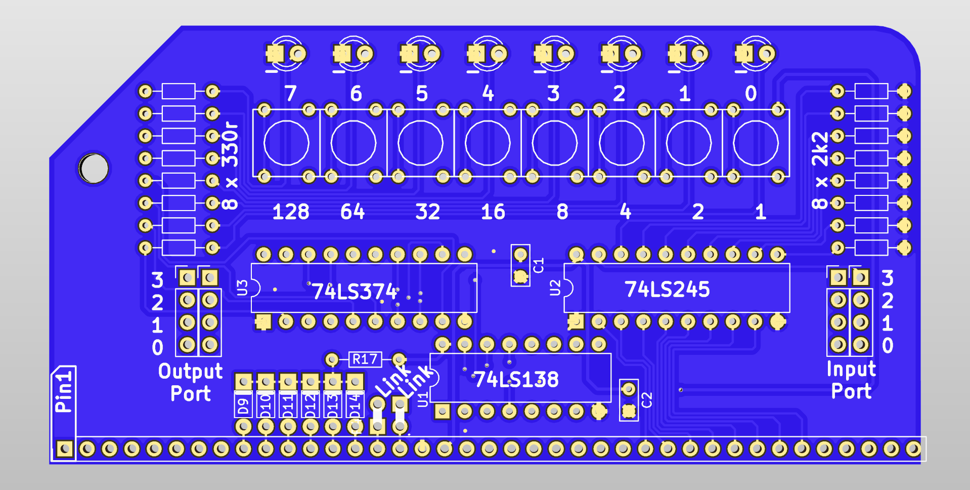
All address lines A0 – A7 along with M1, IOReq and !WR are used to select the multiplexer 74LS138. A2 to A7 are connected via diodes to the enable pin !G2A, such that any of these address lines going high will disable the chip. A0 and A1 are used for selecting the output of the 74LS138, thus the address of this module is 0b00000000, 0b00000001, 0b00000010 or 0b00000011 (0, 1, 2 or 3)
The 74LS138 is capable of 8 lines of switching, although for this board, only 2 (1 input and 1 output) are used. Typically port 0 will be used, but this is selectable from 0 – 3 by soldering links where indicated on the PCB. A0, A1 and !WR are used to select which one of the 8 outputs is enabled.
For further information on port addressing, see Peripheral Addressing post
A 74LS245 transceiver is used to read (!Dir connected to ground) 8 spst tactile switches. These switches are pulled low by 2k2 resistors and when the Chip Enable pin is pulled high, the value of these 8 switches are put on the data bus
Similarly, a 74LS374 flip-flop will read the data bus when the Chip Enable pin is pulled high, and output the values on 8 LEDs via 330 ohm resistors. This value is latched, so when the CE pin is no longer high, the output stays to what it was last set to.
Click image below for schematic in PDF format

In BASIC the port can be read with the INP(0) command which will return a number from 0 to 255, and written to with OUT 0,x where x is the number to output from 0 to 255
In assembly language, the mnemonics in a , (0) and out (0) , a do the same function
Example BASIC program where the buttons are read and their value displayed on the lights
10 OUT 0,INP(0)
20 GOTO 10
Simple cylon scanner program
10 FOR F=0 TO 7
20 OUT 0,2^F
30 GOSUB 100
40 NEXT F
50 FOR F=7 TO 0 STEP -1
60 OUT 0,2^F
70 GOSUB 100
80 NEXT F
90 GOTO 10
100 FOR X = 1 TO 150 : NEXT X : RETURN


Bill of Materials
- RC2014 Digital I/O PCB
- 40 pin header
- 20 pin narrow DIL socket x 2
- 16 pin narrow DIL socket
- 74HCT245
- 74HCT374
- 74HCT138
- 3mm Green LED x 8
- Tactile Switch x 8
- 2k2 resistor x8
- 330R resistor x 8
- 10k resistor x 1
- 1N4148 diode x 6
- 100nf capacitor x 2