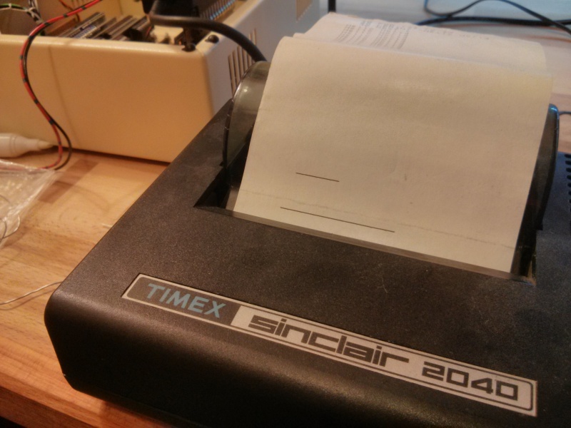
The ZX Printer Interface board does, as the name suggests, allow a Sinclair ZX printer to attach to the RC2014
The wiring between the ZX Printer and a ZX81 (or ZX80 or ZX Spectrum) is very minimal, requiring only the data lines, IORQ, RD, WR and address A2. The original ZX Printer also takes its power from the 9V terminal on the ZX81 bus, although the later Timex/Sinclair 2040 (also sold as Alphacom 32) ones use a separate power supply. So, creating a board for this was fairly trivial.
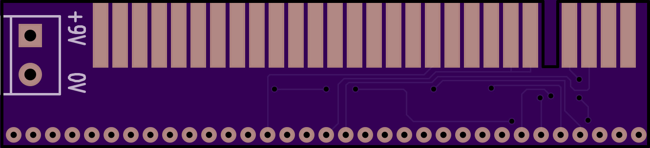
Although I have the 2040/Alphacom version, I added a 9V input terminal to allow compatibility with the original ZX Printer.
Click the image below for schematics in PDF format
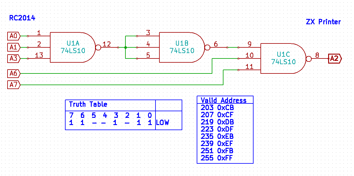
The simplicity of this, however, was also a reason for it to fail. Due to it only using address line A2 LOW, any port that used A2 (for example, port 0,1,2,3,8,9,10,11,16…251), would clash. The only device I had plugged in was the Serial I/O, which used port 80. So, yes, that clashed! This would, of course, work fine if the only other devices plugged in didn’t use A2 LOW in their address space, but I decided to use a more specific address for the printer to avoid this situation.
With a single 74SL10 (3 x triple input NAND gate) it’s possible to select a much more specific address. Using address lines A0, A1, A3, A6 & A7 it can be narrowed down to port 203, 207, 219, 223, 235, 239, 251, 255. That’s 8 ports of the address space it uses, not 128 of them!
Slipping this inbetween the RC2014 and ZX Printer interface was pretty easy with a little strip of Veroboard. It is things like this that make the generic backplane and connectors all worthwhile!

The printer only uses data bits D0, D1, D2, D6 and D7 to drive it, where;
- D2 High = Stop the motor. Low = Start the motor
- D1 High = Motor on slow speed (unless D2 is high)
- D7 High = Power to stylus
- D6 Low if printer connected, otherwise high
- D0 Low/High from encoder disc
So, for example
LD A, 0x04
OUT (0xCB) , A
would start the motor on high speed.
Initial tests from BASIC, using very crude timing meant I was able to create lines of different lengths. This page will be updated when I have a written a proper driver for it in assembly language.