Sorry, this is hastily done due to time constraints right now. Will be fleshed out with more info soon.

Important facts;
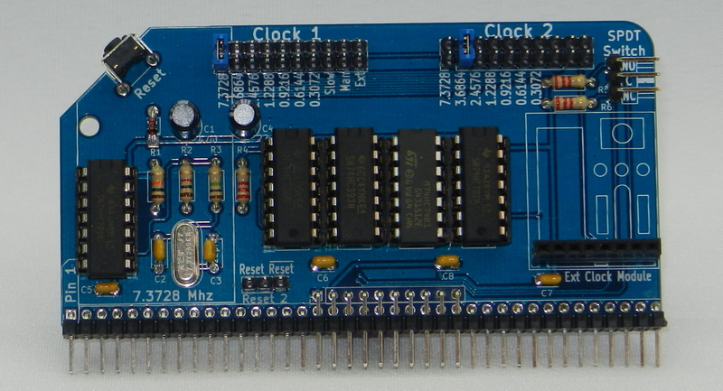
Fast clock runs at 7.3728 Mhz. With 68B50 or SIO/2 UART this will give a baud rate of 115,200. This can be divided down for other baudrates as follows;
- 2 = 3.6864Mhz = 57600bps
- 3 = 2.4576Mhz = 38400bps
- 6 = 1.2288Mhz = 19200bps
- 8 = 0.9216Mhz = 14400bps
- 12 = 0.6144Mhz = 9600bps
- 24 = 0.3072Mhz = 4800bps
Slow clock runs at approx 6-10hz. For other frequencies, change the resistor and/or capacitor
Manual clock runs needs a SPDT switch connected to 3 pin header. Note that this is clock cycles for the CPU, not instruction stepping.
External clock can be fed in to pin 4 on the 8 pin header, or one of the original clock modules can be piggybacked on the board.
The Clock 1 header connects to the regular clock pin on the backplane and drives the CPU and Serial Module. Speed is set by connecting a jumper at the appropriate position.
The Clock 2 header connects to the Clock2 pin on the extended header. Use either a double right-angle pin header for the module with a Backplane Pro, or add a 10 pin header and use a jumper cable for non-extended header backplanes. As per Clock 1, set the speed with a jumper. Note that Slow, Manual and External are available, but wasn’t room to indicate this on the silkscreen.
If only a 7.3728Mhz clock signal is required, then only the components within the outline on the left hand side of the module need to be fitted and a link should be soldered on the 7.3728Mhz pads of the Clock 1 header, and, optionally on the Clock 2 header too.
The reset circuit has been upgraded to allow for an automatic reset to be triggered shortly after power is applied to the RC2014. Either the active low reset or the active high reset signal can be connected to the Reset2 pin on the enhanced bus – although be aware that this pin is also used by the Pageable ROM and 64k RAM for the page signal, so you can only have one or the other.
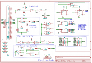
Circuit diagram

Bill of materials
Dual Clock Single Speed
RC2014 DUAL CLOCK PCB 1
40 pin RA Header 1
14 pin narrow DIL socket 1
74HCT04 1
7.3728 Mhz Xtal 1
22pf ceramic cap 2
100nf 1
1M resitor 1
1k resistor 1
10K resistor 1
47uf 25v electrolytic 1
1N4148 1
RA Tactile Switch 1
Dual Clock Multi Speed
RC2014 DUAL CLOCK PCB 1
40 pin RA Header 1
14 pin narrow DIL socket 5
74HCT04 1
74HCT00 1
74LS393 1
74HCT74 1
74LS02 1
7.3728 Mhz Xtal 1
22pf ceramic cap 2
100nf 4
1M resitor 1
1k resistor 1
10K resistor 1
2K2 resistor 3
47uf 25v electrolytic 1
22uf 25v electrolytic 1
1N4148 1
RA Tactile Switch 1
10 pin header 5
8 Way SIL Socket 1
3 pin RA header 1
Errata for V2.0
U1 should be a 74HCT04, not a 74HCT14 as indicated by the silkscreen
U2 should be a 74HCT02, not a 74HCCT02 as indicated by the silkscreen
A bridge must be soldered between pin 2 on U3 and pin 13 on U4 as indicated below
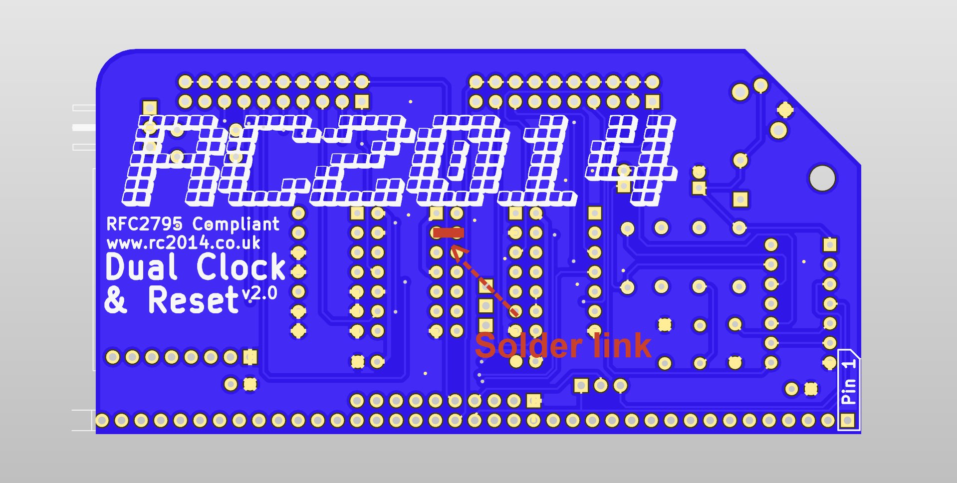
Later (V2.1 boards and onward) will not need this modification