The RC2014 Mini II is the evolution of the RC2014 Mini. A small Z80 based Single Board Computer (SBC) that can boot straight in to BASIC, FORTH or a Z80 assembler. With the optional new RC2014 Mini II CP/M Upgrade Kit it can run CP/M from compact flash cards.
This page is for the RC2014 Mini II. For the original RC2014 Mini please refer to this page
Having all the functions on a single board reduces the component count and therefore the amount of soldering compared to the modular equivalent. It also allows more efficient use of the logic chips. This efficiency comes at the expense of upgradability, where the modular option allows for any of the functions to be replaced if required. The likelihood of wanting to swap major components should be weighed up to determine if the modular RC2014 Classic II or the RC2014 Mini II approach is right for you.

The assembly guide for the Mini II can be found here
Hardware
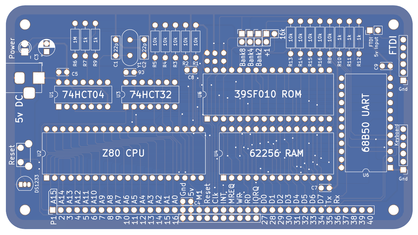
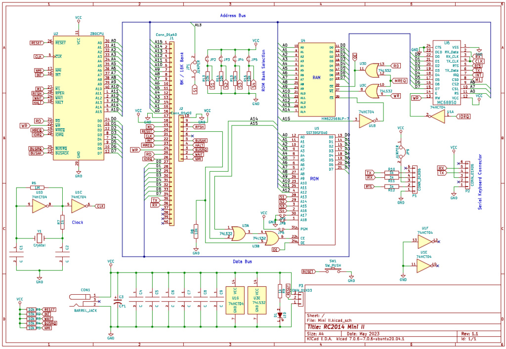
The Zilog Z80 is the heart of the RC2014 Mini II. Through the data bus, address bus and control signals it connects to the ROM, RAM, Serial I/O and the expansion bus. Some of the control signals like NMI, WAIT, BUSRQ, HALT, BUSAK and RFSH are not used by the Mini II, however there are some expansion modules that make use of them, so these are on the 10 pin Enhanced Bus header. The other signals from the Z80, as well as serial Tx and Rx are bought out on the 40 pin Standard Bus header.
The 32k 62256 RAM sits in the upper 32k of the 64k address space of the Z80 from 0x8000 to 0xFFFF. Address line A15 will only go high when the upper 32k is being accessed, so this goes via a NOT gate to an active low Chip Select on the RAM. The RD, WR and MREQ signals are ANDed in to the Output Enable and Write Enable so that the RAM knows if it should be reading the data bus and storing it at the address on the address bus, or if it should be writing the contents of that address on to the data bus.
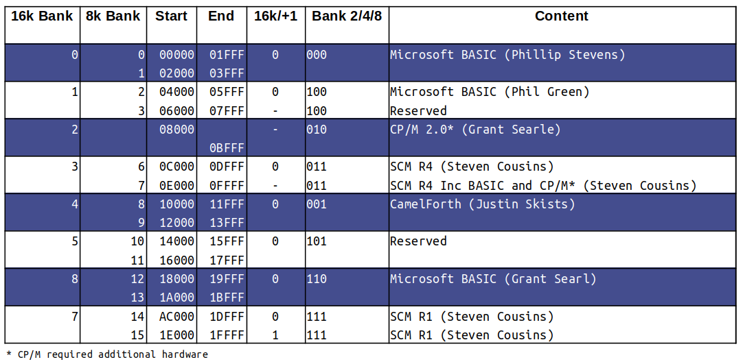
A 128k flash ROM, the SST39SF010 sits at the bottom of the address space. Depending on the setting of JP1/JP2, either 8k (from 0x0000 to 0x1FFF) or 16k (from 0x0000 to 0x3FFF) is available to the Z80. The jumpers JP3/JP4/JP5 determine which of the 8 16k banks within the ROM are active, and it is the job of JP1/JP2 to set this as either the full 16k, or the lower 8k or upper 8k within that bank. JP1/JP2 can either be horizontal (16k), omitted (lower 8k) or vertical (upper 8k). See below for ROM contents and specific jumper settings. The active low Chip Enable pin is selected when A14 AND A15 are both low (ie address below 0x4000 needs to be read) and also that the PAGE pin on the Enhanced Bus header is low. The Page function isn’t active within the RC2014 Mini II, however the RC2014 Mini II CP/M Upgrade Kit can drive this pin and page in an additional 32k of lower RAM to run CP/M
A MC68B50 Asynchronous Communications Interface Adapter (ACIA) gives the RC2014 the ability to talk to the outside world through a serial port. Address A0, A6 and A7 put the 68B50 on port 0x80 and 0x81. When these addresses are selected, along with IORQ and M1, the chip is active, and will read or write depending on the state of the WR signal. The IORQ pin from the 68B50 goes back to the INT pin on the Z80 so it can trigger an interrupt when it has data in its input buffer.
The Tx, RX and RTS from the UART go to a 6 pin FTDI style serial port, along with ground. The 5v pin of this port is via a jumper so the Mini II can be powered via the FTDI adapter. If the barrel socket is used to power the Mini II the jumper can must be removed. Tx, Rx, ground and 5v also go to another 6 pin header which have the Tx and Rx swapped. This is for a serial keyboard.
The standard FTDI colours are marked on the silkscreen on the back of the PCB, which are;
- Black GND
- Brown CTS
- Red VCC
- Orange TXD
- Yellow RXD
- Green CTS
The 7.3728MHz crystal and 22pf load capacitors uses a couple of inverters to generate a squarish wave form to run the CPU. The UART is run from the same clock as the Z80, which with a 7.3728MHz crystal will communicate at 115200 baud.
The reset line is pulled high through a resistor, and pushing the reset button will ground the active low Reset pin on the Z80. A DS1233+5 will also keep the Z80 in reset state on power-on until the voltages have stabilised, meaning the Z80 should always boot cleanly.
There is a footprint for an electrolytic capacitor C3 near the power socket. This is not required unless you are using a particularly low quality 5v supply. Rather than fit a 100uf capacitor to fix the issue you should probably consider changing your power supply. Mobile phone USB chargers work great!
There are also 3 cuttable links next to the ROM. The 128k 39SF010 can be replaced with a 256k 39SF020 or a 512k 39SF040, however, to access the banks above 128k you will need to cut the links and add jumpers to 5v. It is anticipated that 128k of ROM images should be sufficient for even the most enthusiastic user – however feel free to Contact Me with your use case if you need specific instructions on what to do here.
ROM Selection Jumpers
The RC2014 Mini II comes with 3 variations of Microsoft BASIC, 2 versions of Small Computer Monitor and also CamelForth on ROM. Setting the jumpers will determine which of these boots when the RC2014 is powered on.
If no jumpers are fitted then 32k Microsoft BASIC will boot.
If all 3 jumpers are fitted (with or without the JP1/JP2 jumper in either setting) then Small Computer Monitor will boot.
If the 3 jumpers are set to 0 0 1 then FORTH will boot.

Software
Microsoft BASIC was used by many computers in the late 70s and early 80s, including TRS80, Apple II, Commodore PET, VIC-20, C64, IBM PC Jr etc. There are 3 variants supplied with the Mini II.
The Grant Searle 32k Microsoft BASIC is derived from the NASCOM 2, with modifications by Grant Searle. These modifications essentially remove commands that relate to NASCOM 2 specific hardware and also adds commands to deal with Hex or Binary numbers. For more information see the manual for NASCOM 2 BASIC and Grant Searles modifications
The Phillip Stevens 32k Microsoft BASIC builds on the Grant Searl version with a hex loader, MEEK and MOKE statements for simple Z80 programming and a couple of other features and improvements. Information on this can be found here.
Also derived from Grant Searles BASIC, the Phil Green 32k BASIC variant has a monitor ROM included which gives a lot of flexibility over programming in both BASIC and assembly. Information on this can be found here.
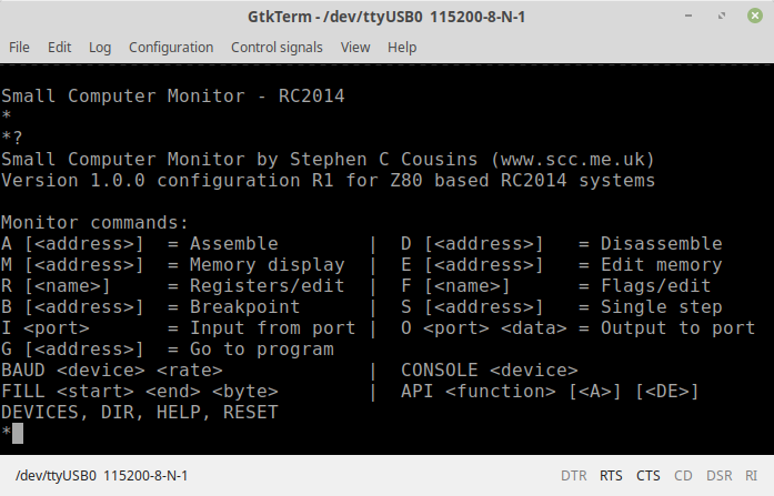
Small Computer Monitor (SCM) is a Z80 monitor ROM which allows you low level access to the RC2014. This includes assembling and disassembling Z80 assembly code, direct port access, memory manipulation, as well as single stepping through code, examining registers and setting break points. It also features the ability to load Intel .hex files in to memory. Information on SCM can be found here, and the tutorial is highly recommended.
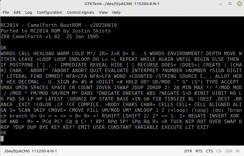
CamelForth is a traditional FORTH programming language, originally created by Brad Rodriguez. This particular variant has been modified from James Bowmans port to boot from ROM, support Intel .hex files as well as some extra Words added. More information on this can be found here.
Using The RC2014 Mini II
Before powering on your RC2014 for the first time, take a moment to double check all solder joints for solder bridges, dry joints, or missed joints. Ensure all components are orientated the right way and chips are pressed in firmly. Set the jumpers for either BASIC, FORTH or SCM. If you are powering your RC2014 from the barrel jack, ensure the 5v jumper by the FTDI port is removed. Alternatively, if you are powering it from the FTDI cable, ensure that jumper is fitted.
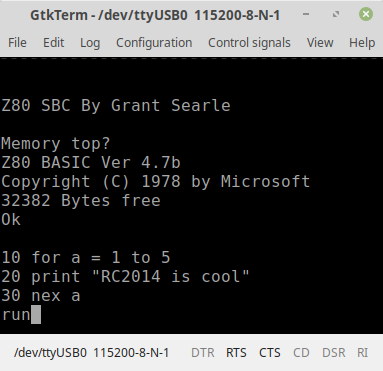
Connect your FTDI cable to your computers USB port, and fire up your favourite terminal emulator. (If you don’t have a favourite terminal emulator, then TeraTerm for Windows, GtkTerm for Linux, or MiniCom for Mac are recommended). Ensure that your terminal emulator is using the serial port that your FTDI device shows up as, and is set to 115200 baud, 8 bits, No Parity, 1 Stop Bit (8-N-1 is the default on most devices). Connect the FTDI header to the RC2014, in accordance with the colour pinout as described above. You should then be greeted with the welcome message for either BASIC, FORTH or SCM.
If booting to BASIC for the first time, it will ask for Memory Top? Just hit return here for the full 32k to be available. Subsequent resets will ask for Cold or Warm start. Cold clears the memory before starting, Warm retains whatever was in memory before the reset. You’re then ready to start programming in BASIC!
If booting to SCM you will be greeted with a welcome message and a * prompt. Hit ? [return] for a summary of commands. You’re then ready to start programming in Z80 assembly language!
If booting to CamelForth you will be greeted with a welcome message. Hit the Return for the OK prompt. Type WORDS to get a list of what words are in its current dictionary. Note that CamelForth is case sensitive.
Troubleshooting
If your RC2014 Mini II fails to boot up, don’t worry. Most faults can be traced visually, and few faults lead to permanent damage. All the chips should be cool to the touch, though, so if it is not booting and one of them is getting hot, remove the power quickly!
Read through the Troubleshooting Guide here for pointers on what to look out for. If you are still having issues, use the Contact me link, or visit the RC2014-Z80 Google Group. Be prepared to explain exactly what the issue is, and what steps you have already taken. It may help to provide clear photos of the assembled board too.
Bill of materials
1 x RC2014 Mini II PCB
1 x 40 pin wide DIL socket
1 x 32 pin wide DIL socket
1 x 28 pin wide DIL socket
1 x 24 pin wide DIL socket
2 x 14 pin narrow DIL socket
1 x 40 Way SIL Socket
1 x 10 Way SIL socket
1 x 6 Way SIL socket
1 x 6 pin RA header
1 x 2 pin RA header
1 x 5×2 RA header
4 x jumper
1 x 2.1mm power jack
1 x 3mm green led
1 x RA Tactile Switch
1 x 7.3728 MHz Xtal
1 x DS1233-5+
2 x 22pf ceramic cap
6 x 100nf
5 x 1k resistor
10 x 10k resistor
1 x 1M resistor
1 x 74HCT04
1 x 74HCT32
1 x Z80 CPU
1 x ST39SF010
1 x 62256 RAM
1 x MC68B50
1 x USB Barrel Lead