The Front Panel Kit comprises of a Front Panel Module and a Front Panel I/O Panel, and can be used to set the booting mode for RomWBW and also monitoring disk activity. This can then be fitted to any enclosure with holes drilled in the appropriate place, or to a purpose made front panel such as the one for the 110*250*190 Blue Box enclosures.

Front Panel Module
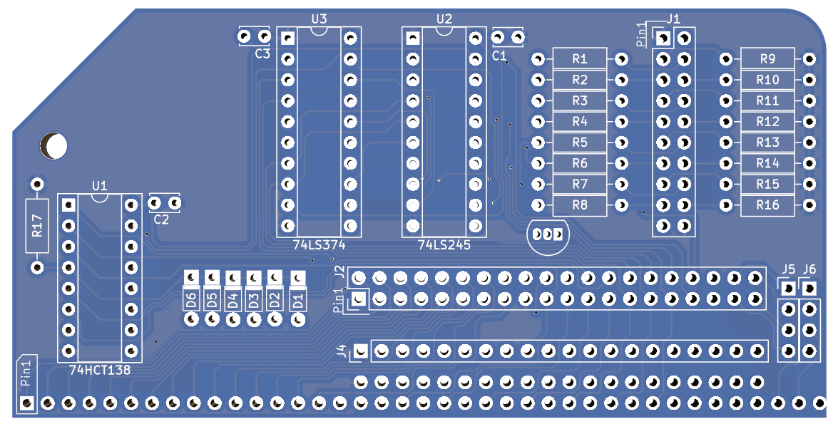
The Front Panel Module sits in the RC2014 and connects to the Front Panel I/O Board via ribbon cable. The main circuitry is almost identical to the Digital I/O Module with a 74HCT138 monitoring for a read or write to I/O Port 0. This state is only true when A0 to A7 is low, !IORQ is low and M1 is high. If the !WR line is low then it is performing a write, and the 74HCT374 which drives the LEDs is enabled. Alternatively, if the !WR line is high then it is performing a read and the 74HCT245 which drives the switches is enabled.
When the ‘374 is enabled, the state of the address bus is put on its output pins which go to the front panel LEDs via 1k resistors.
When the ‘245 is enabled, the state of the 8 switches on the front panel are put on the data bus. There are pull down resistors to ground so that any switches no on will read as low.
A DS1233 Reset Supervisor is fitted to hold the RC2014 in reset until the power on voltage has stabalised, thus giving a clean boot. The reset signal is also sent to the front panel where the RC2014 can be manually reset.
The LEDs, switch inputs, reset switch and also 5v power are all connected to a 2×10 pin header that can be routed to the Front Panel I/O Panel via a ribbon cable.
All 36 of the RC2014 Standard Bus signals are routed to a 2×20 pin header. The spare 4 pins on this header can either take the additional USR signals or up to 4 signals on the RC2014 Enhanced Bus. This allows for a 40 way ribbon cable, such as an IDE hard drive cable, to be used with a compatible Rear Panel which converts the signals back to an RC2014 header. The aim of this is to allow for an expansion slot outside of an enclosure which may be more convenient than opening the enclosure. Note that the bus is not buffered, so cable length should be minimised, and proper operation is not guaranteed for all modules.
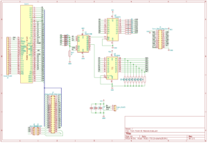
Click image to open PDF schematic
Assembly follows the same procedure as with other RC2014 modules. Follow the silkscreen and start with the lowest components and ensuring that the ICs are orientated correctly.
Front Panel I/O Panel
The Front Panel I/O Board carries the 8 LEDs for Port 0, the 8 toggle switches for Port 0, a power LED and a spring return switch for the reset signal.
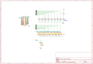
Click image to open PDF schematic
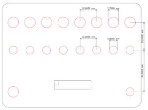
Click image to open PDF of dimensional drawing
Click here to download zipped SVG of dimensional drawing
The Front Panel I/O Panel can either be mounted in to an existing enclosure or fitted in to the panels specifically designed for certain enclosures, such as the 110 x 250 x 90 Blue Box enclosures. If you are using your own enclosure, the files linked to above will give you a PDF image which can be printed out at 100% scale and used as a template, or an SVG file that can be used to generate a tool path for laser cutters, CNC routers or extruded for a 3D printer.
Assembly is pretty straightforward, although please see this assembly guide for a step by step approach.
RomWBW Usage
From version 3.4.0 RomWBW has had support for a front panel assembly.
Initially the LEDs will light in sequence as it goes through starting the system, initialisation, detection and so forth to console activation. Once booted the LEDs will represent disk activity for the disk units from 0 to 7, depending what is available on your machine.
The switches set the initial boot parameters of the RC2014. From left to right, the first switch, CRT/Serial has no effect on RC2014 machines. The Pri/Sec switch selects which of the serial ports to use at boot.
If the Auto/Menu switch is set to Menu then RomWBW will boot to the regular menu where you can use the keyboard to select what to boot in to. However, if Auto is set, then the configuration of the next 5 switches will dictate what RomWBW will boot to.
Booting from ROM, you have a choice of 8 options, which are selected by the 3 right-most switches. Booting from disk, you have a choice of floppy disk or hard disk, and the boot slice is selected by the 3 right-most switches.
For a more detailed description, see Chapter 3 of the RomWBW User Guide
Usage on a non-RomWBW RC2014
This module was designed to take advantage of the advanced features of RomWBW. However, it is fundamentally a Digital I/O Module on Port 0. So whichever RC2014 you have, you can set the LEDs and read the switches just as you can with a Digital I/O Module. See the description here https://rc2014.co.uk/modules/digital-io/

Bill of materials – Front Panel I/O Kit
1 Front panel IO panel PCB
9 5mm red LED
9 5mm LED Bezel
8 MTS-102 Toggle Switch
1 MTS-123 reset switch
2 10 pin header
1 1k resistor
1 10×2 10cm IDC cable
1 Front panel IO Module PCB
1 74HCT138
1 74HCT245
1 74HCT374
1 16 pin narrow DIL Socket
2 20 pin narrow DIL Socket
1 40 pin RA header
2 10 pin header
3 100nf
6 1n4148
8 1k resistor
8 2k2 resistor
1 10k resistor
1 DS1233-5+