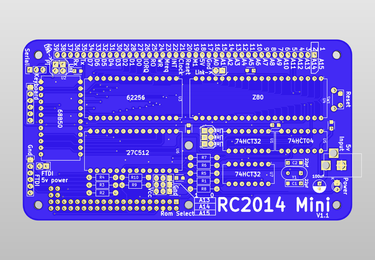
The RC2014 Mini is a single board computer which combines the CPU, ROM, RAM, Clock, Serial I/O and Pi Terminal of the classic modular RC2014 on to a single PCB.

Having all the functions on a single board reduces the component count and therefore the amount of soldering compared to the modular equivalent. It also allows more efficient use of the logic chips. This efficiency comes at the expense of upgradability, where the modular option allows for any of the functions to be replaced if required. The likelihood of wanting to swap major components should be weighed up to determine if the modular or the Mini approach is right for you.

The form factor has been designed such that it can plug in to the existing Backplane5 or Backplane8, thus reducing the amount of slots required compared to the modular approach. (Note that although it is exactly the same size as the Backplane5, and can neatly stack on top, this will block access to the other 4 slots unless they come out underneath!). The other modules, such as the Digital I/O Module can either plug straight in to the RC2014 Mini, or used via a backplane.
The 6 pin FTDI connector on the left allows the RC2014 Mini to be operated from a desktop or laptop computer via terminal emulator software such as PuTTY, Teraterm or Screen
There is a keyboard connector on the left hand side which allows the Universal Micro Keybaord (in serial mode) to be stacked on top. If doing this, however, please be aware that the resistor, capacitor and reset switch on the keyboard will have to be soldered off to one side to fit snugly, or extra deep connectors can be used to avoid this). This connector and form factor also opens up the option of creating a hex keyboard and 7-seg display PCB for a more traditional ROM Monitor type set up. The UMK cannot be used at the same time as an FTDI connection
There is a 2×20 way header which allows a Pi Zero to be connected below to allow HDMI output and USB keyboard input. This works with the same Pi image as the Pi Zero Serial Terminal. There is a jumper to set if keyboad input is to come from the Pi or from the FTDI/UMK.
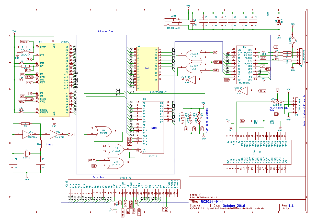
Overall schematic is shown below (click image for .pdf version), but for the detailed operation of each segment, see the appropriate module page.
Assembly Instructions here RC2014 Mini Assembly Guide
Bill of materials
1 x RC2014 Mini PCB
1 x 24 pin wide DIL socket
2 x 28 pin wide DIL socket
1 x 40 pin wide DIL socket
3 x 14 pin narrow DIL socket
1 x Z80 CPU
1 x 27C512 EPROM BASIC
1 x 62256 RAM
1 x MC68B50
1 x 74HCT04
2 x 74LS32
1 x 7.3728 Mhz Xtal
2 x 22pf ceramic cap
6 x 100nf cap
4 x 1k resistor
1 x 1M resitor
1 x 10k resistor
1 x 22k resistor
1 x 2k2 resistor
1 x 330r resistor
1 x 3k3 resistor
1 x 3mm green led
1 x RA Tactile Switch
1 x 2 pin header
4 x 3 pin header
2 x 20 pin header
1 x 40 pin header
1 x 40 pin RA header
1 x 6 pin ra header
1 x 2 x 20 pin socket
1 x 40 Way SIL Socket
1 x 6 way SIL socket
5 x jumper
1 x 2.1mm power jack
1 x USB Barrel Lead