I recently had a customer contact me to say his RC2014 kit was not working, and asked if the ROM had definitely been programmed. It is the first time I had been asked that, but despite sending out over 3000 ROMs so far without sending out a blank one yet, how could I be 100% sure that one hadn’t slipped through?

This question got me thinking. Obviously the easy answer is for the customer to put the ROM in an EPROM programmer and read it – but I don’t know if the customer has an EPROM programmer. Sending out a replacement ROM would normally be another option, but due to the Christmas shutdown, huge postal delays, and the customer being on a different continent, that wasn’t going to be a quick solution.
It turns out that there is a very simple way to prove the existence of something on the ROM. It won’t prove that the right image is on the ROM, or that there isn’t corruption on it, but it does answer the question of whether or not it has been programmed.
The theory is quite simple. Read the first byte of the ROM. A blank ROM will have 0xFF (0b11111111) in every location. The images for the RC2014 ROMs all start with either 0xF3 (0b11110011) or 0xC3 (0b10100011). So selecting address 0 should give either 11110011 or 10100011 on the datalines.

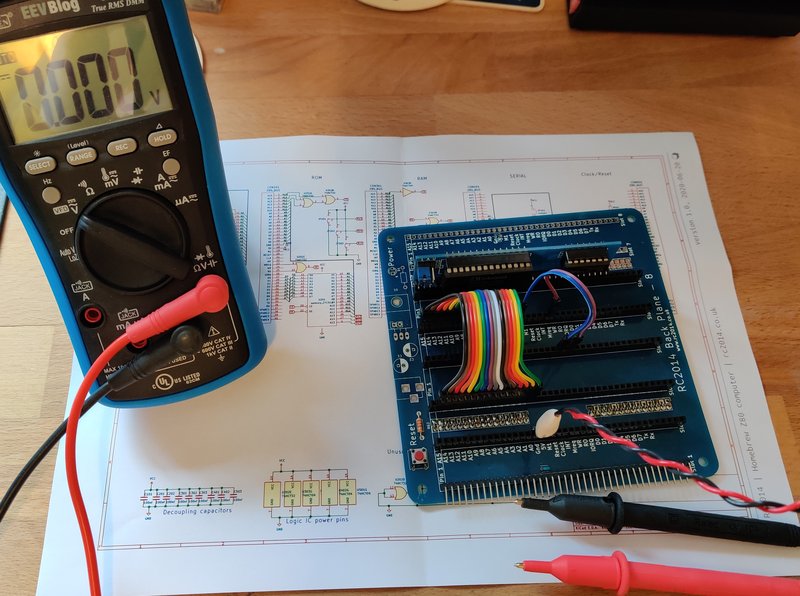
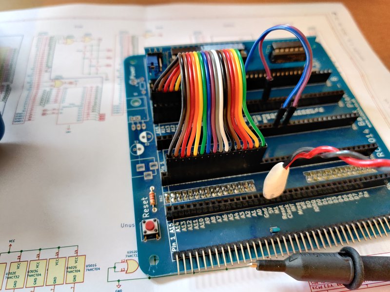
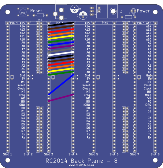
Thankfully, this is actually very simple in practice, and can be done with just 18 jumper cables! Firstly, remove all modules from the backplane except for the ROM Module. Set the three jumpers on the ROM Module to 0. To ground all the address lines, place a jumper cable from the Gnd pin on Slot 3 of the backplane to A0 on Slot 4. Then another from A0 on Slot 3 to A1 on Slot 4, and so on all the way up the address pins. RD and MREQ need to be held low too, so add a cable from Gnd on Slot 4 to MREQ on Slot 3, and from MREQ on Slot 4 to RD on Slot 3. Take a multimeter on its continuity setting and just confirm that A0-A15, MREQ and RD are all connected to ground.

Then swap your multimeter to DC voltage, connect power to the backplane, and read the voltages on D7 – D0. They should be a mixture of 0v and 5v that correlate to either 11110011 or 10100011. If they are all 5v, then it’s a pretty good assumption that the ROM has not been programmed!
Note that if you do not have jumper cables, then ordinary solid core wire can be used, or even humble paper clips! Alternatively, if you have a spare 40 way pin header, then soldering a wire across all the address lines to ground, and also connecting RD and MREQ to ground will also work.
This was written specifically for the RC2014 Classic, however the same applies to the RC2014 Classic ][, the RC2014 Plus and the RC2014 Pro. The theory also applies to the RC2014 Mini, although you will have to get a bit more creative with the wiring :-)
