Ok, so tomorrow the Summer RetroChallenge 2014 starts, so I thought it would be a good idea to bring you up to speed with what I’ve got so far so that you know where I’m starting from. I will also outline where I’ll be taking things for the RetroChallenge as well as where this project may go in the future.
So, in December 2013 I started poking around the internets for some ZX80 info, and I stumbled upon Grant Searles website. More specifically, he had the schematics for a Z80 based computer and a ROM with Microsoft BASIC on it. So, over Christmas I got out my breadboards and built it up pretty much as per the schematic.
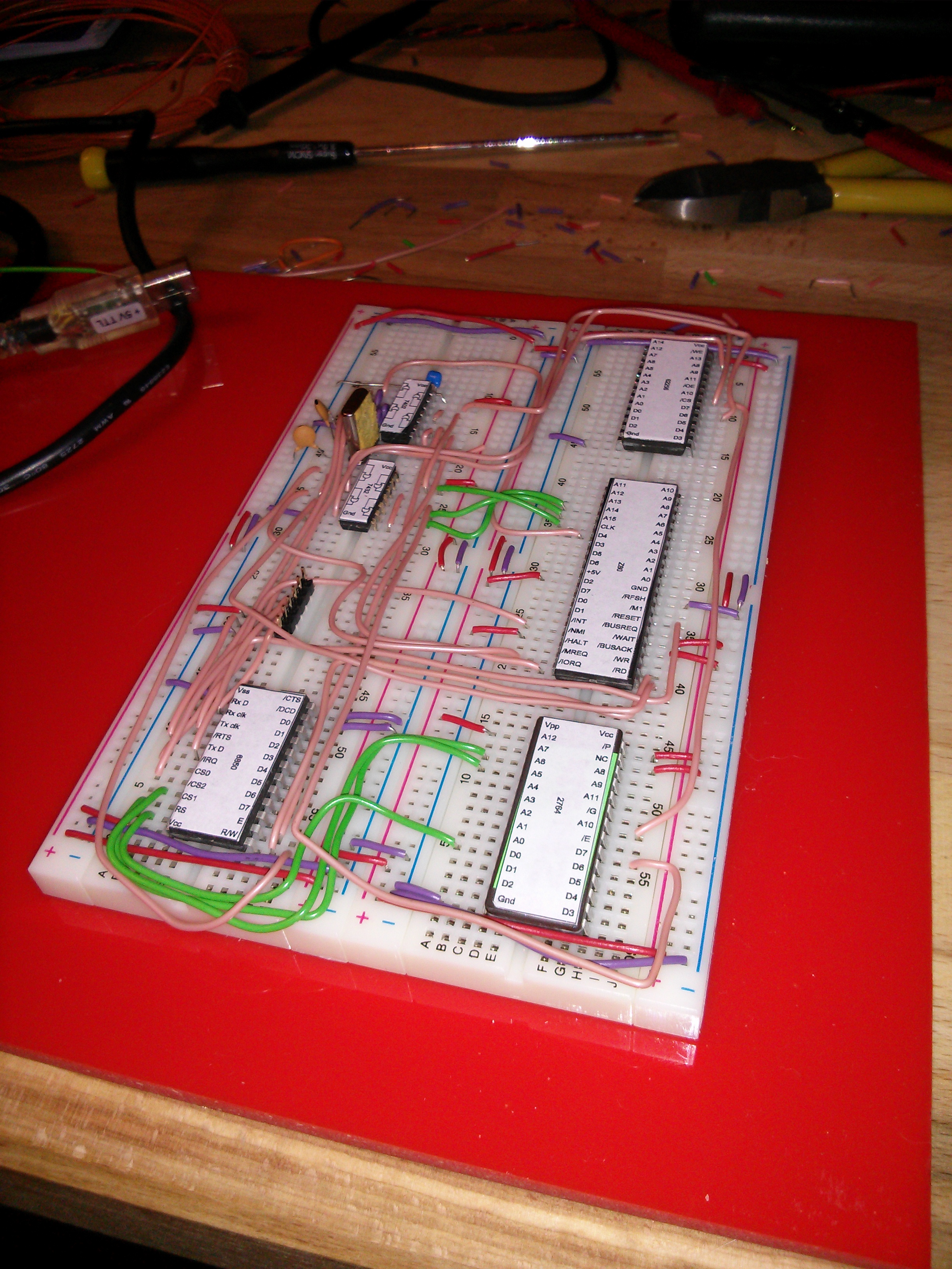
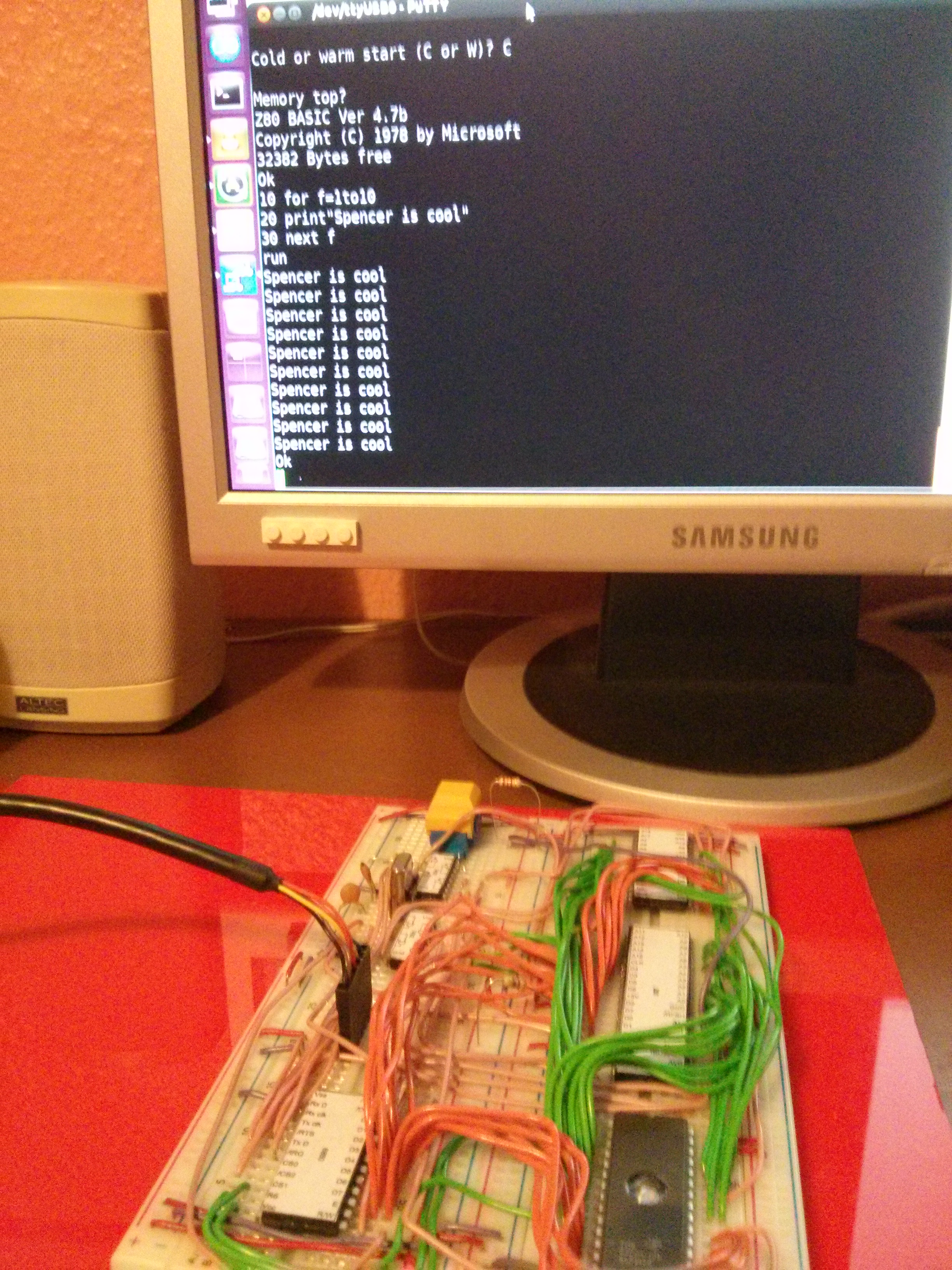
There was a few hiccups along the way, but on Christmas Eve I attached a serial cable to my PC, fired up a terminal session and was able to run small BASIC programs!
Over the next couple of months I added a LCD screen and an old AT keyboard so it could stand alone without a PC to communicate with. These were interfaced via an (Arduino) ATMEGA328 – and yes, the irony of this little £2 chip being more powerful than the Z80, yet only reading keyboard and writing to LCD was not lost on me! I went on to add some basic I/O for reading switch inputs and lighting LEDs.
Whilst there is an artistically crazy beauty in the breadboard approach, with 16 address lines and 8 data lines winding their way to every corner of the board, it doesn’t make for easy modification or troubleshooting. Inevitably every time I transport it, a wire comes lose so getting it going again often takes a while. So I’ve decided to transpose it to the more permanent medium of Printed Circuit Board.
Whilst all of this could easily go on to one PCB quite happily, I have decided to go with a very modular approach so individual segments can be added or modified as I go along. Individual boards will be easier to troubleshoot too. Oh, and for me, REAL computers are made up of multiple boards plugged in to a common backplane!
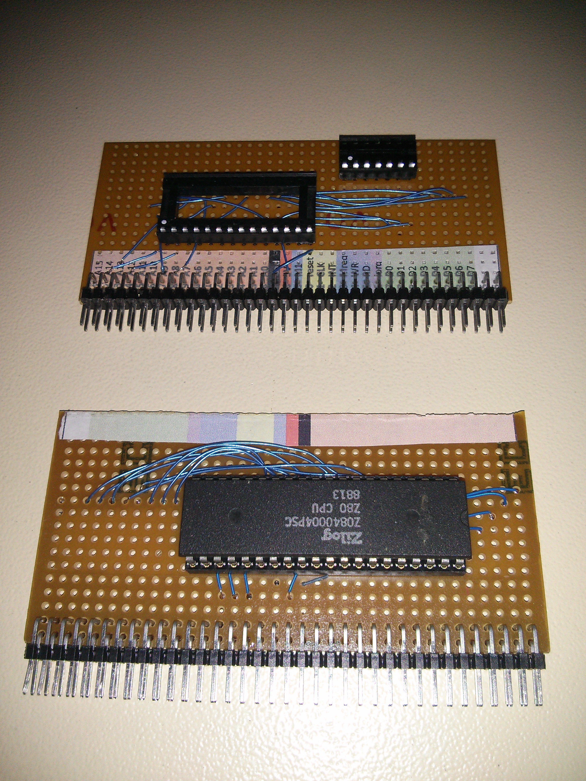
A couple of months ago I looked at how the backplane issue was tackled back in the day. There were a few common standards, the most popular of which was the S100, although they all shared one thing in common; expensive connectors! If I was going to split this in to many different boards, I didn’t want to be spending a fortune on each one just for the connectors. So I decided to simplify things with 0.1″ pitch header sockets on a Veroboard backplane.
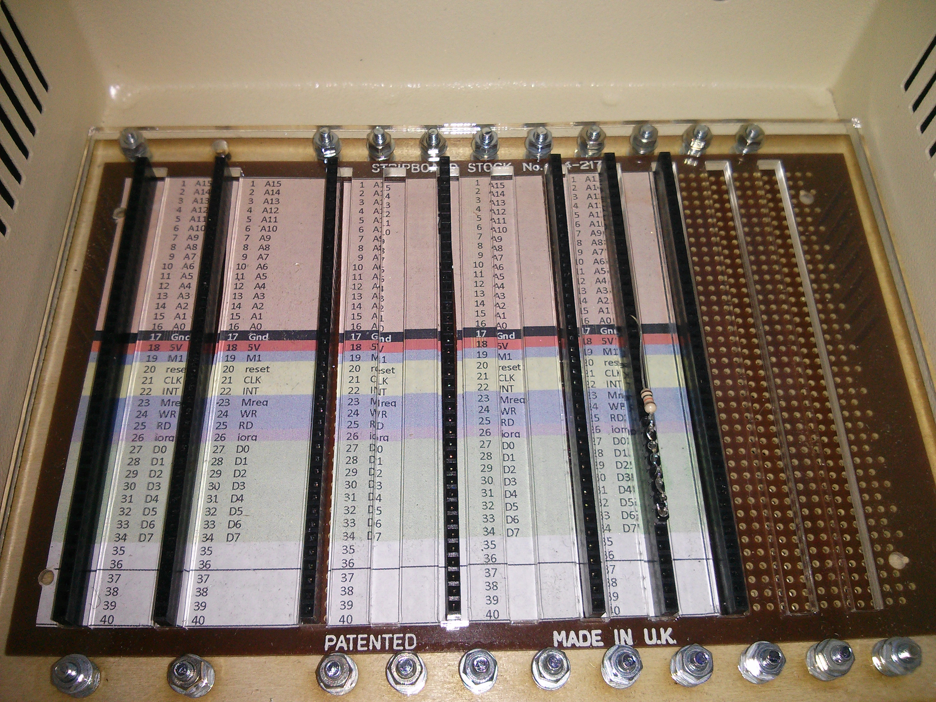
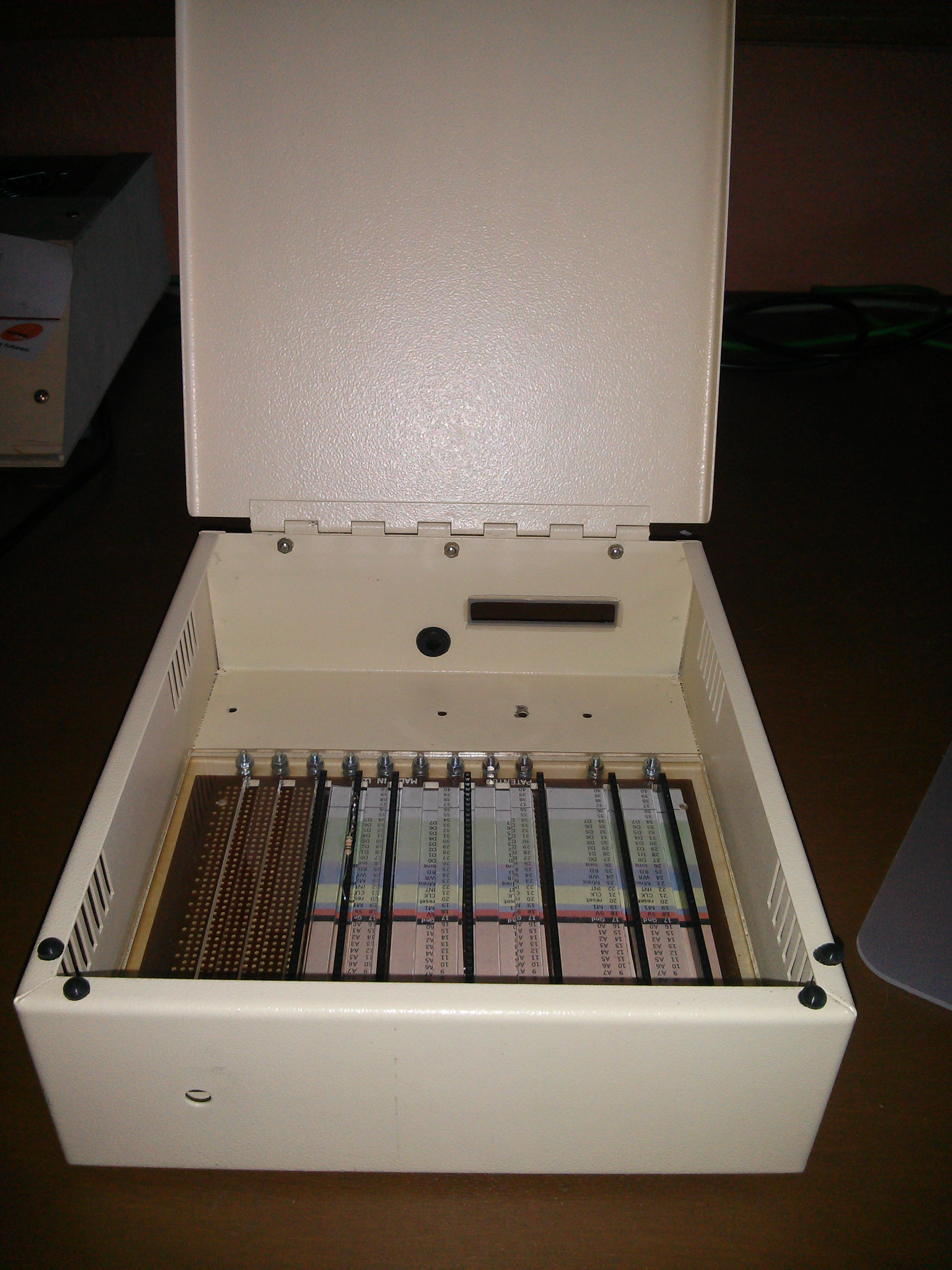
The sockets are 40 way, although at the moment I am only using 34 of those. It is inevitable that there’ll be some extra data lines of some sort! I’ve already found myself a wonderfully retro box in BBC Model B beige too!
I did make up a couple of plug in cards from Veroboard too, but with the amount of delicate connections needed, this doesn’t really feel like much of a step up from the breadboard.
I have had a couple of PCBs made in recent months by OSHPark and they are excellent quality boards at a great price. Pretty quick turnaround too. I managed to grasp the basics of PCB design in KiCad so I should be able to get things done fairly efficiently. There will be components and footprints to design in KiCad, and, as OSHPark charges by the square inch, I’ll be wanting to keep the sizes down to an absolute minimum.
The individual daughter boards I’ll be wanting to make are;
- Processor
- ROM (eprom MS BASIC)
- ROM (eeprom for easy programming)
- RAM
- Clock (7.3728Mhz)
- Clock (debounced button for manually stepping through code)
- Clock (variable speed timer to run slowly without manually pushing a button)
- Blinkenlights (Each of the address, data and clock lines to have a LED)
- Serial I/O
- KeyboardLCD (ATMEGA328 just like the breadboard version)
- TV Output
- Switch Input (Individually addressed input lines)
- LED Output (Individually addressed output lines)
Of course, only a few of these are needed for basic operation, and initially I will only be making what is required to meet the challenge.
Then there’s the programming. Oh, the programming! As I’ve mentioned before, I’m not a programmer, so diving in to Z80 assembler language is going to be hard going. Whilst the boards are off for fabrication I can use an online Z80 emulator to learn the fundamentals, and hopefully, but the time they’re done, I’ll be ready to run some code on the real machine. I’ve got electrically erasable programmable read only memory (eeprom) chips that I can use, then erase and program again when it doesn’t work. And as long as I’ve got the button based clock board done, I can step through the code one instruction at a time an hopefully interpret the Blinkenlights to see what’s going on.
All in all, I kow it’s going to be quite a learning experience, but I’m sure it’s going to be a fun one (and probably frustrating) too!
Wish me luck!