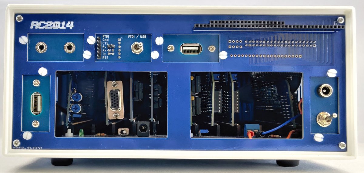
The Blue Box Rear Panel is designed to compliment the Front Panel and provide access to the various ports and controls of the RC2014.
Please note that whilst the modular nature of the RC2014 means that people can customise and build their kit to their own needs, this makes designing a universal rear panel that caters to everybody very difficult. It is inevitable that this panel will not be perfect for everybody. Some modification, wiring, drilling and compromise is to be expected.
The main panel has two access holes that give easy access to the power connectors on the backplane and rear of most modules. Five holes allow for port covers to be fitted so that other connections from the RC2014 can be bought out to the rear. A bus connector is also present that allows an extra module to be fitted externally.

Bus Connector – Standard Bus
To use the external bus connector it must be connected to the Front Panel I/O Module via a 40 way ribbon cable. This is the same cable that IDE hard drives use. Two rows of 20 pins need to be fitted to the Front Panel I/O Module as well as the inside face of the Rear Panel. This will bring all 36 signals present on the Standard Bus out to the connector.

Note that the ribbon cable is not supplied with the kit. It is assumed that anybody that has been using computers for a while has a bunch of them in a shoe box somewhere. Alternatively, they are cheap and easily found online.
Bus Connector – Enhanced Bus
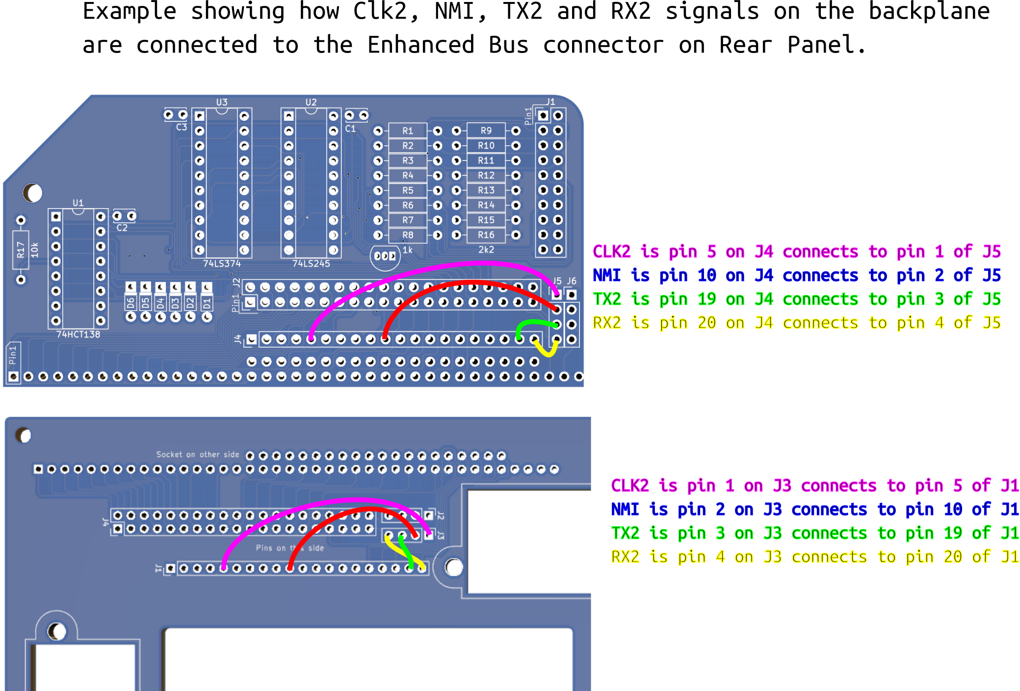
The 40 way ribbon cable brings all 36 of the Standard Bus to the expansion socket. An additional 4 signals from the Enhanced Bus (or last 4 pins of the Standard Bus) can also be present too. To use these an Enhanced Bus connector needs to be fitted on the Front Panel I/O Module. Then each of the 4 signals from the bus need to be jumpered across from J4 to one of the 4 spare pads on J5 of the I/O Module. These 4 signals need to have the corresponding pads jumpered out from J3 to J1 on the Rear Panel PCB. If you know exactly which signals you need, then these links can be made my soldering wires directly to the PCB, but otherwise use header pins and jumper cables for maximum flexibility. In practice, though, you will probably find that there are not many modules that need to be fitted outside the case and also need Enhanced Bus signals.
The example below brings CLK2, NMI, TX2 and RX2 out to the Enhanced Bus on the rear panel. (Click to expand)
Port Covers
The Rear Panel can be provided with blanking plates or pre-drilled plates for a variety of connectors. Alternatively, if you have access to a laser cutter or 3D printer, you can create your own custom port covers. This SVG file can be downloaded and used as a template for laser cutting or 3D printing. The PCB material or acrylic port covers can be easily drilled or cut if you need too.
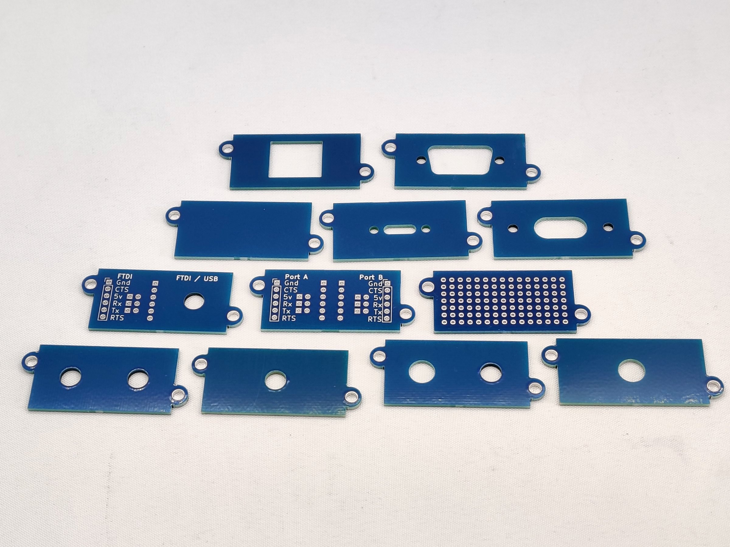
Blank Panel – PCB

This can be used to blank off any unused holes in the rear panel. Alternatively, the FR4 PCB material can be easily drilled for your own custom port cover
6mm hole
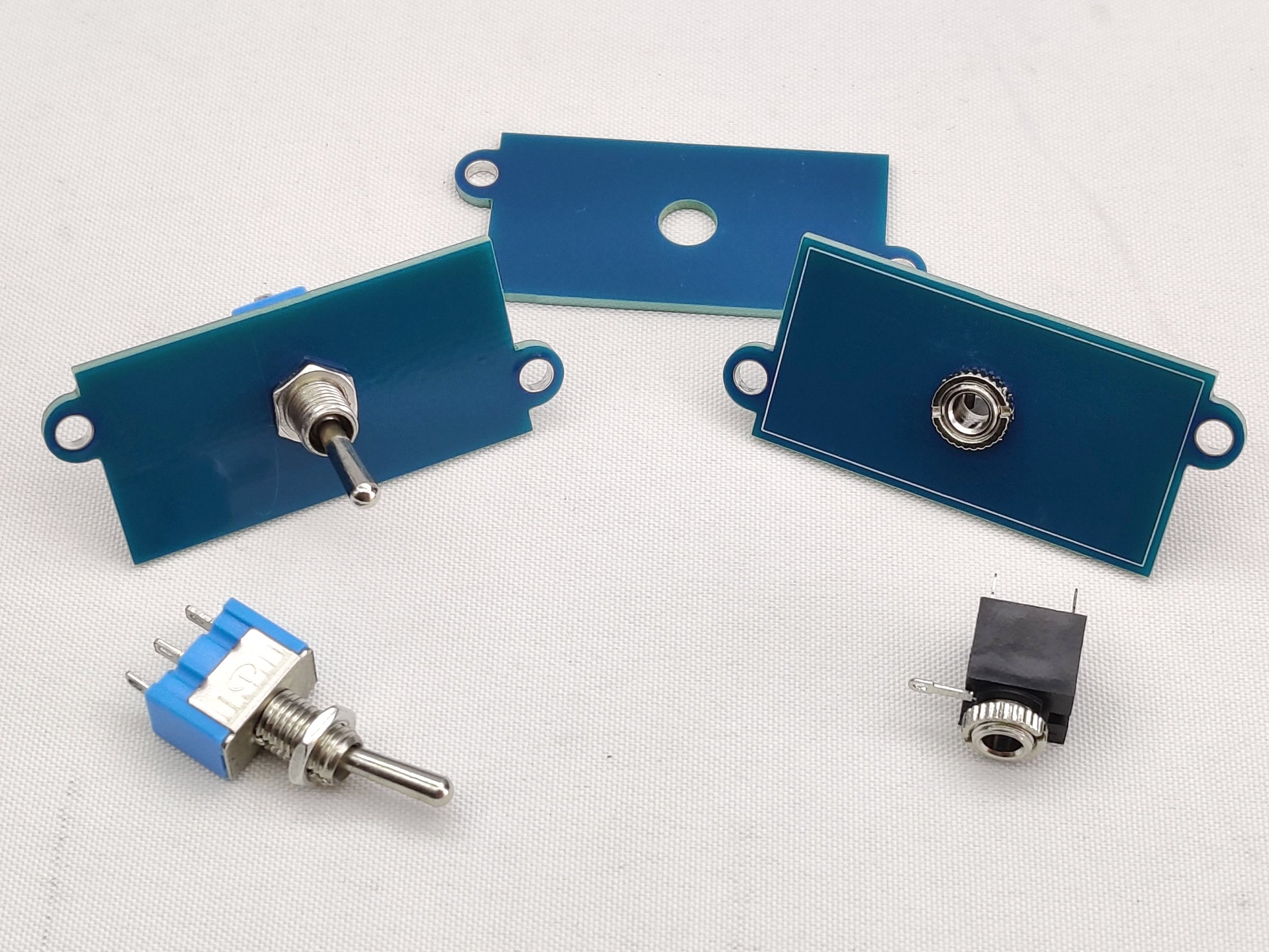
The 6mm hole fits a toggle switch or 3.5mm audio socket perfectly. Great for bringing out the audio from a sound module, or switching the LCD backlight.
Dual 6mm hole
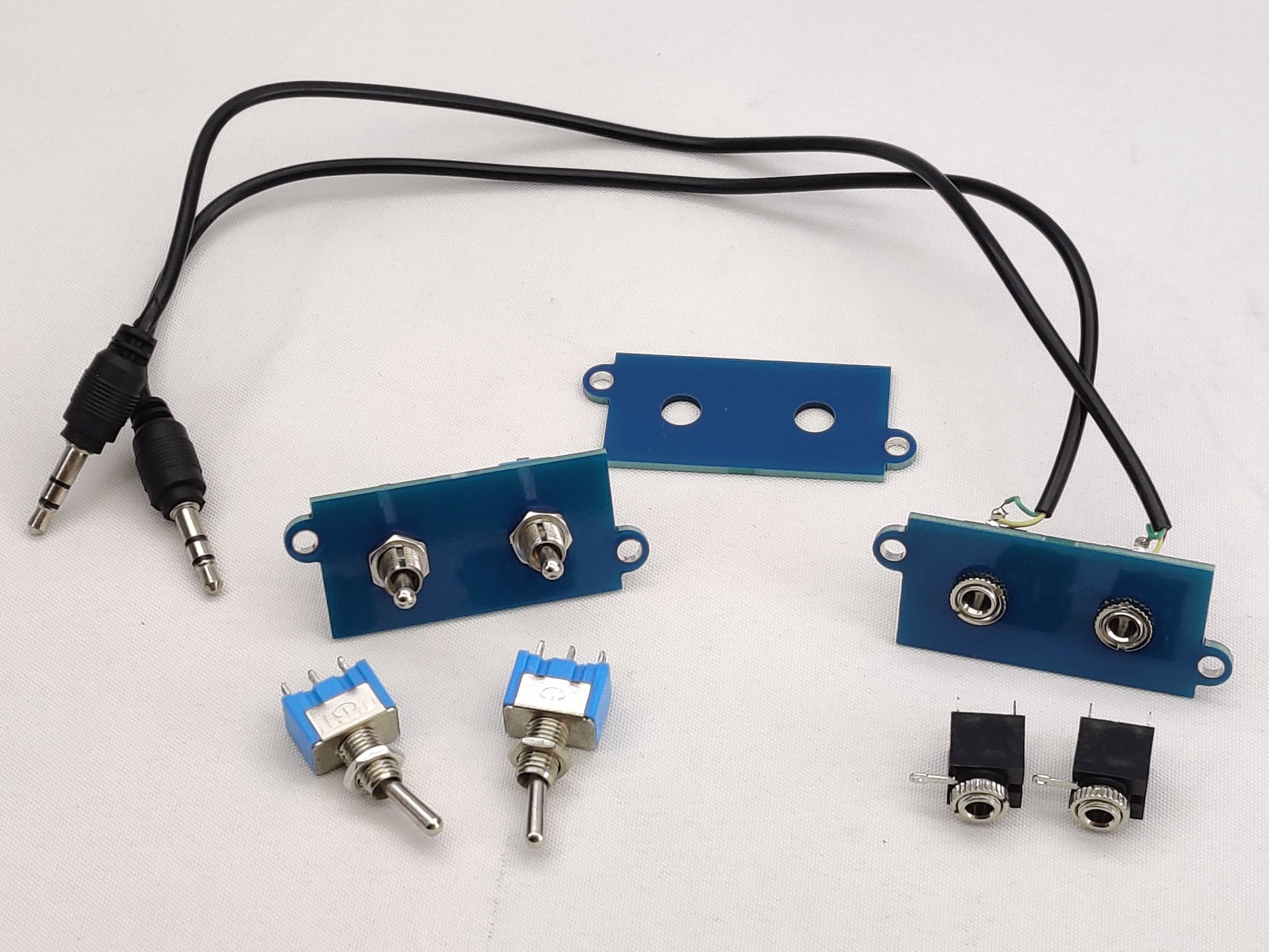
Similar to the 6mm hole above… but there are two of them! Great if you have 2 sound cards, a Dual Paddle Analogue Module, or need two toggle switches.
7.5mm hole
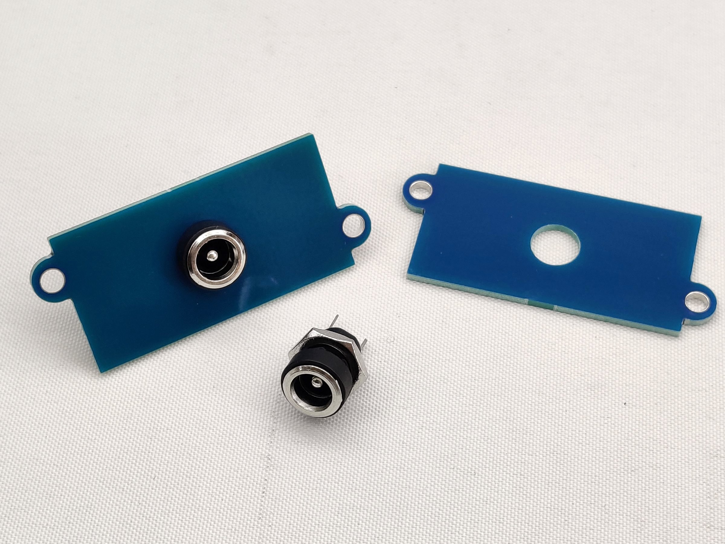
This fits connectors such as a barrel jack power input.
6mm + 7.5mm Hole
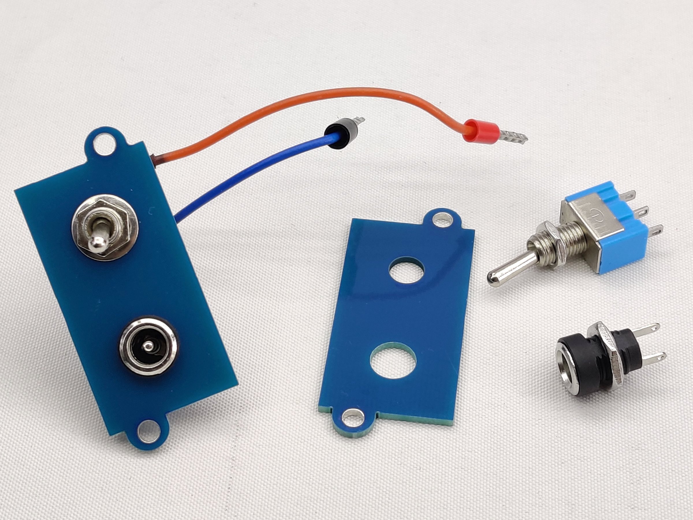
A good use of this panel cover is for switched power input via the 2 screw connector on the backplane. There are probably a lot more options too.
USB A
This is designed for the standard USB A panel mount sockets
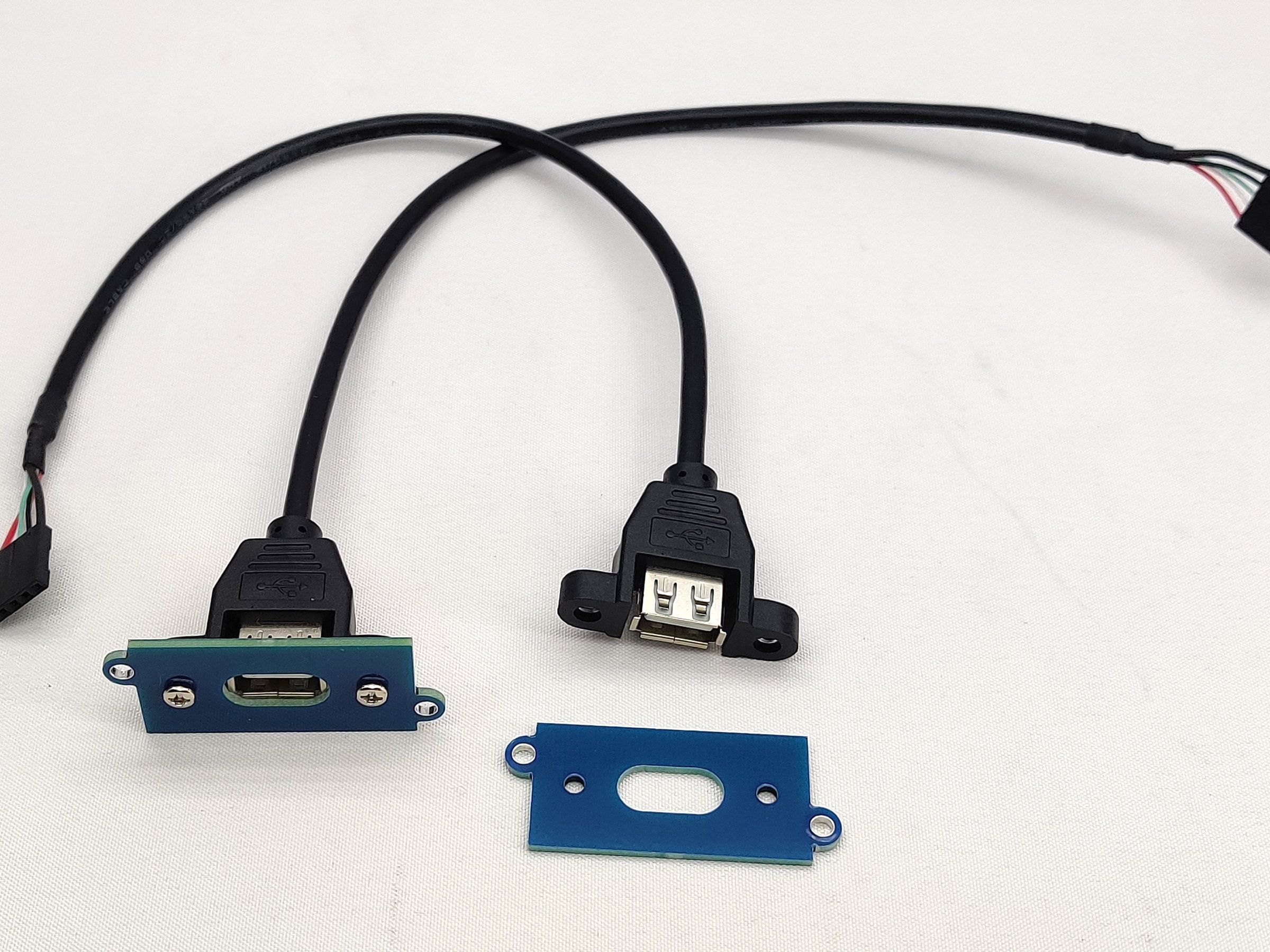
USB C

This can be used with either standard USB C panel mount extensions or the super cute little USB C breakout connectors.
Dual FTDI
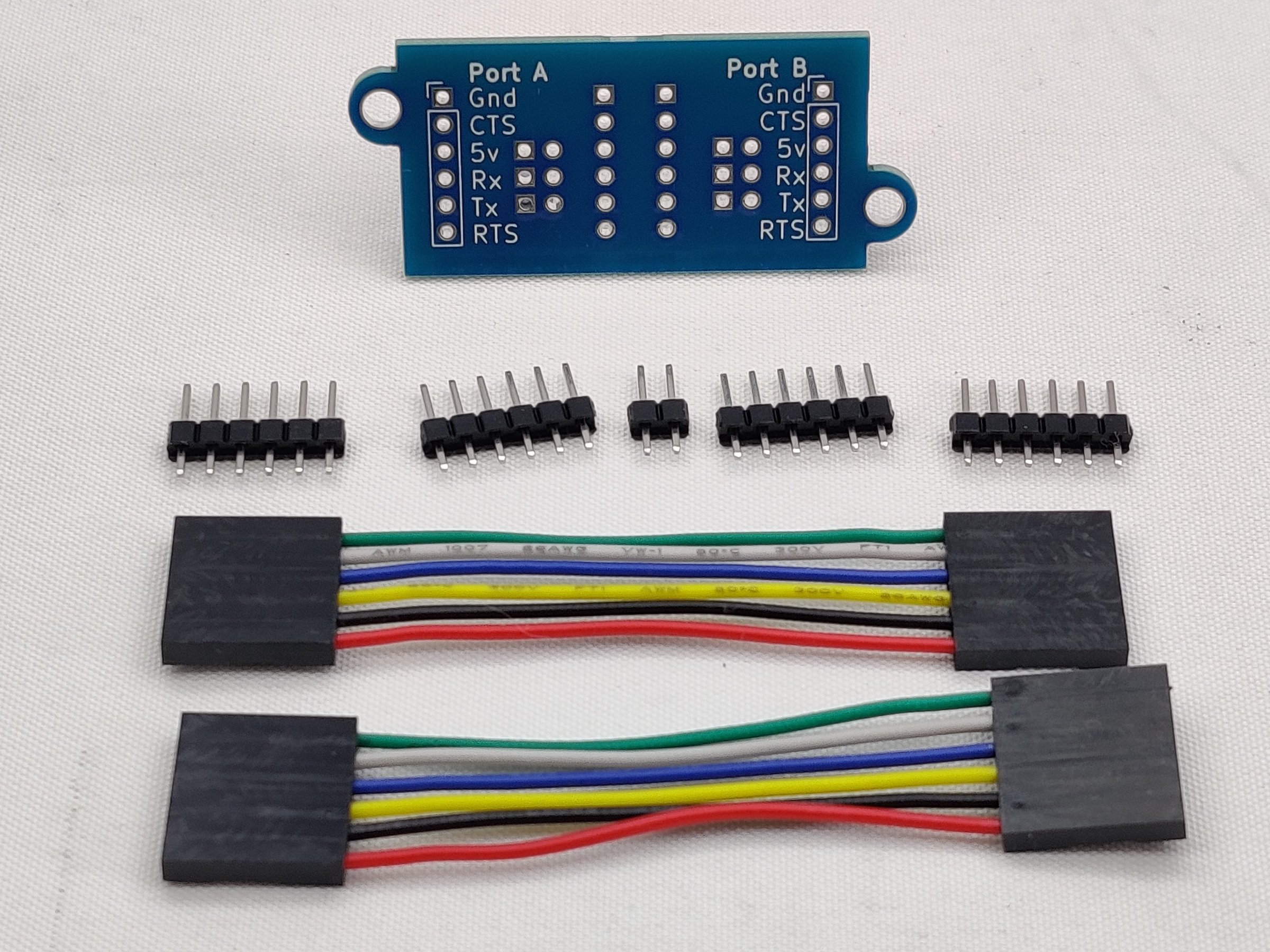
Because both of the FTDI ports of the SIO/2 Module are hard to reach, fitting pins to this module allow you to bring both of those connections out to the rear panel. Fit the center set of pins on the inside of the enclosure and the furthest left/right pins on the outside of the enclosure. The 5v, Tx and Rx signals can be connected via jumpers or permanently soldered bridges.
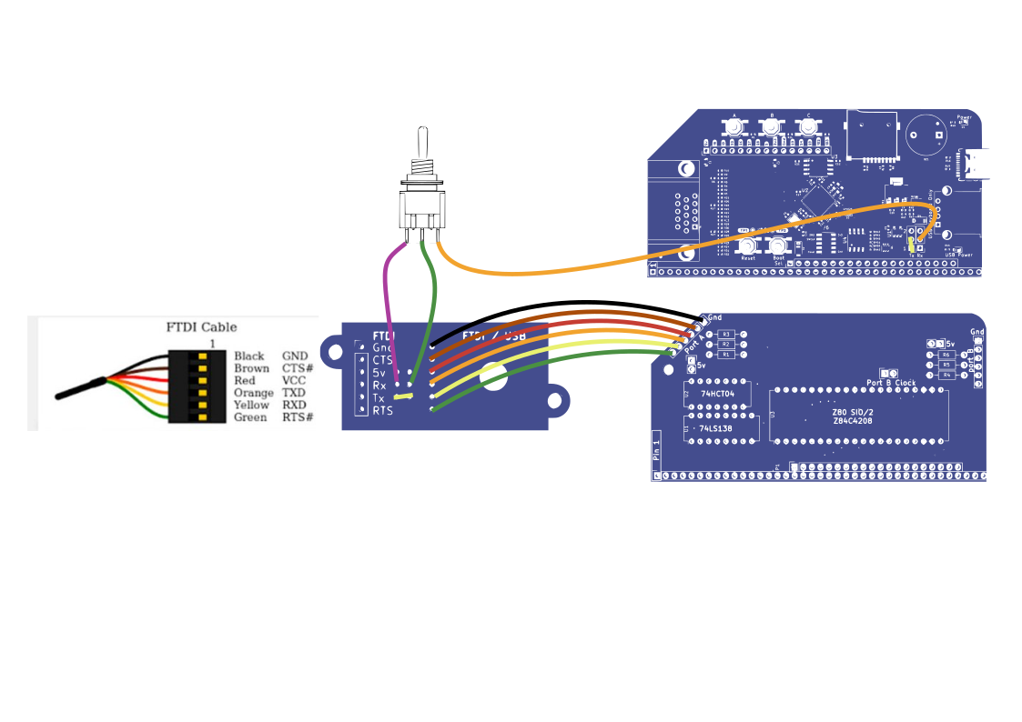
FTDI – USB Switch
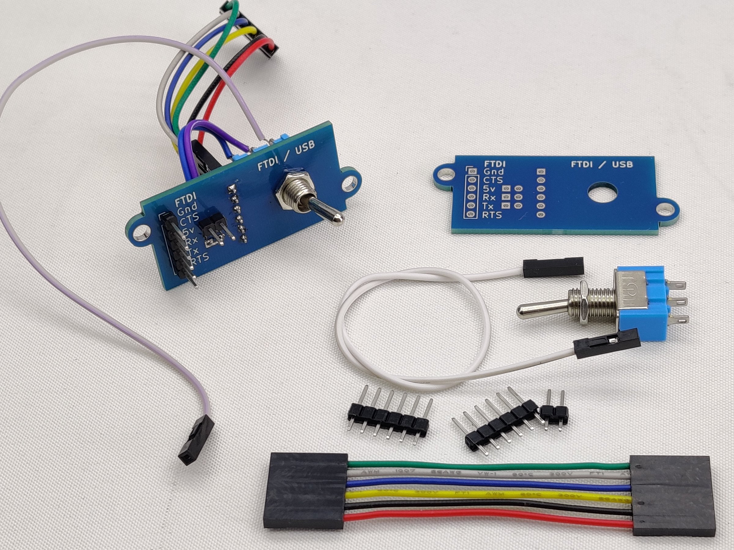
A single FTDI connector and a switch is a great way to use a USB keyboard via an RP2040 VGA Module and still have the option of FTDI input when required. The circuit shown means that there will always be output on both the VGA output and the FTDI Tx pin, but input can be swapped between the USB keyboard and FTDI Rx via the switch. See example below (click to expand).
DE-9
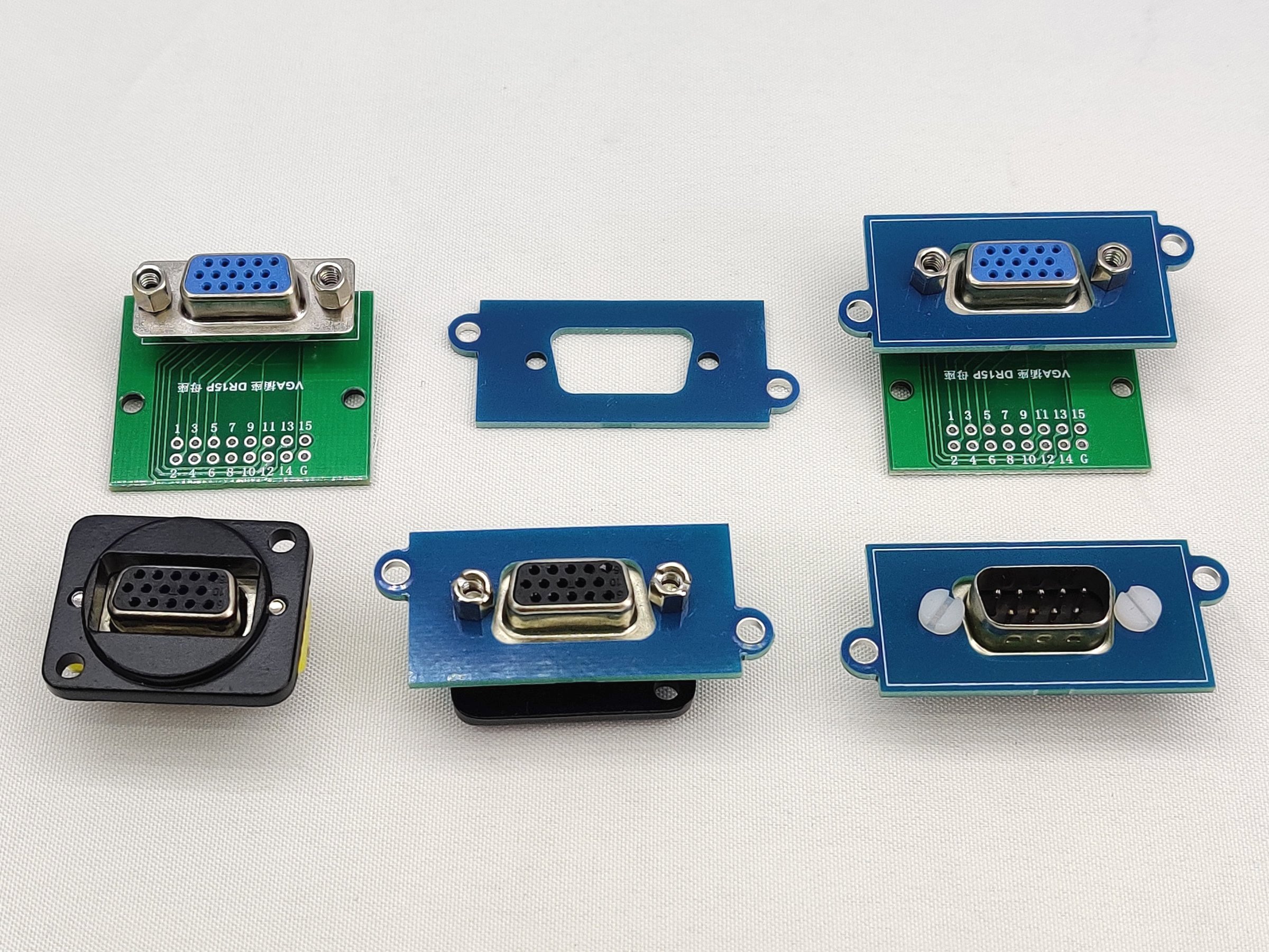
This will fit either a DB-9, such as used for joystick or RS232, or DB-15 as used for VGA
Keystone Module
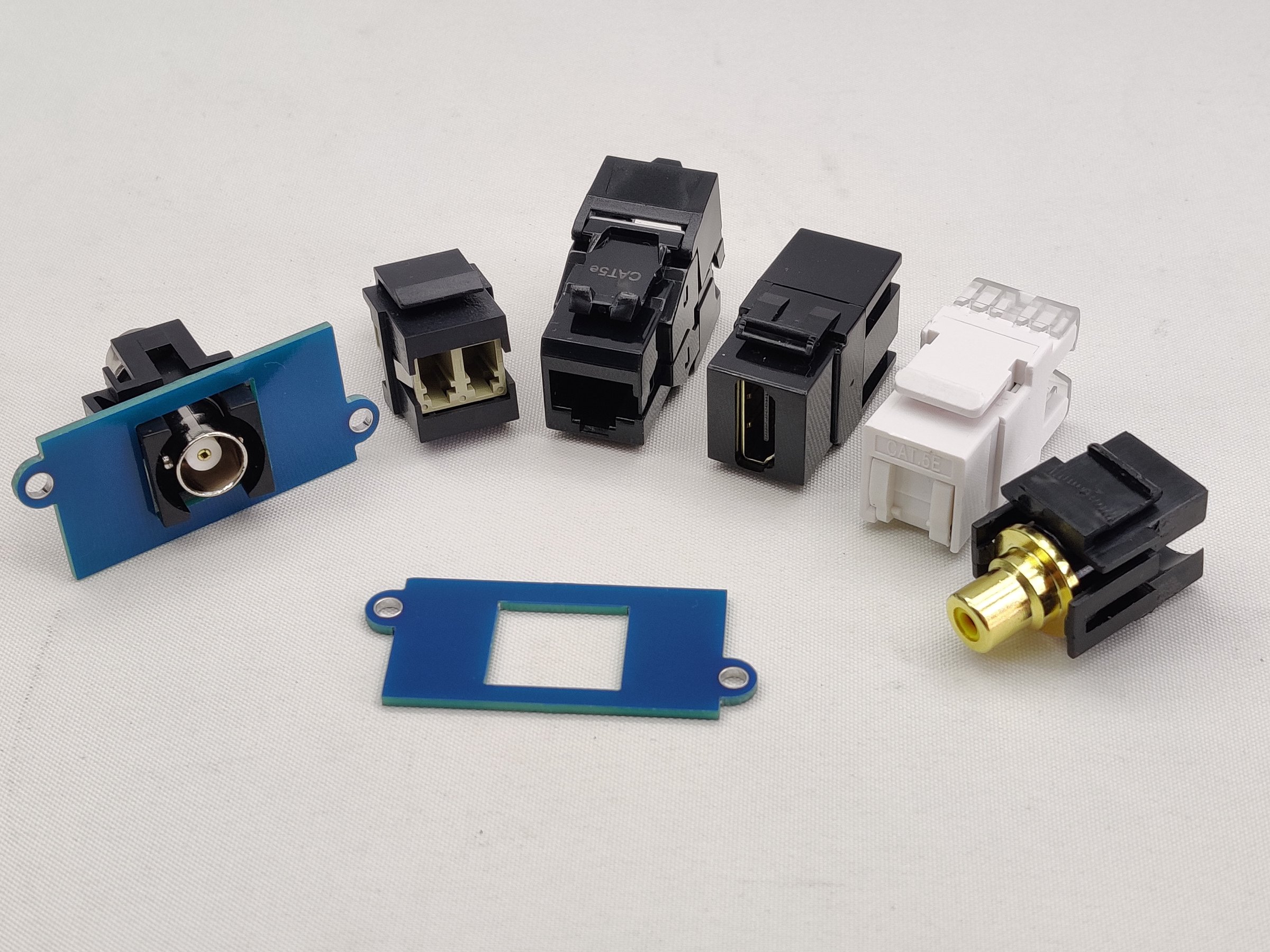
Keystone modules are generally used for CAT6 wiring, but there are a lot of pass-through connectors such as phono, BNC, HDMI, USB that can be very useful at bringing out signals from your RC2014. There are even fiber pass-through for anybody running fiber to their RC2014!
Proto Board
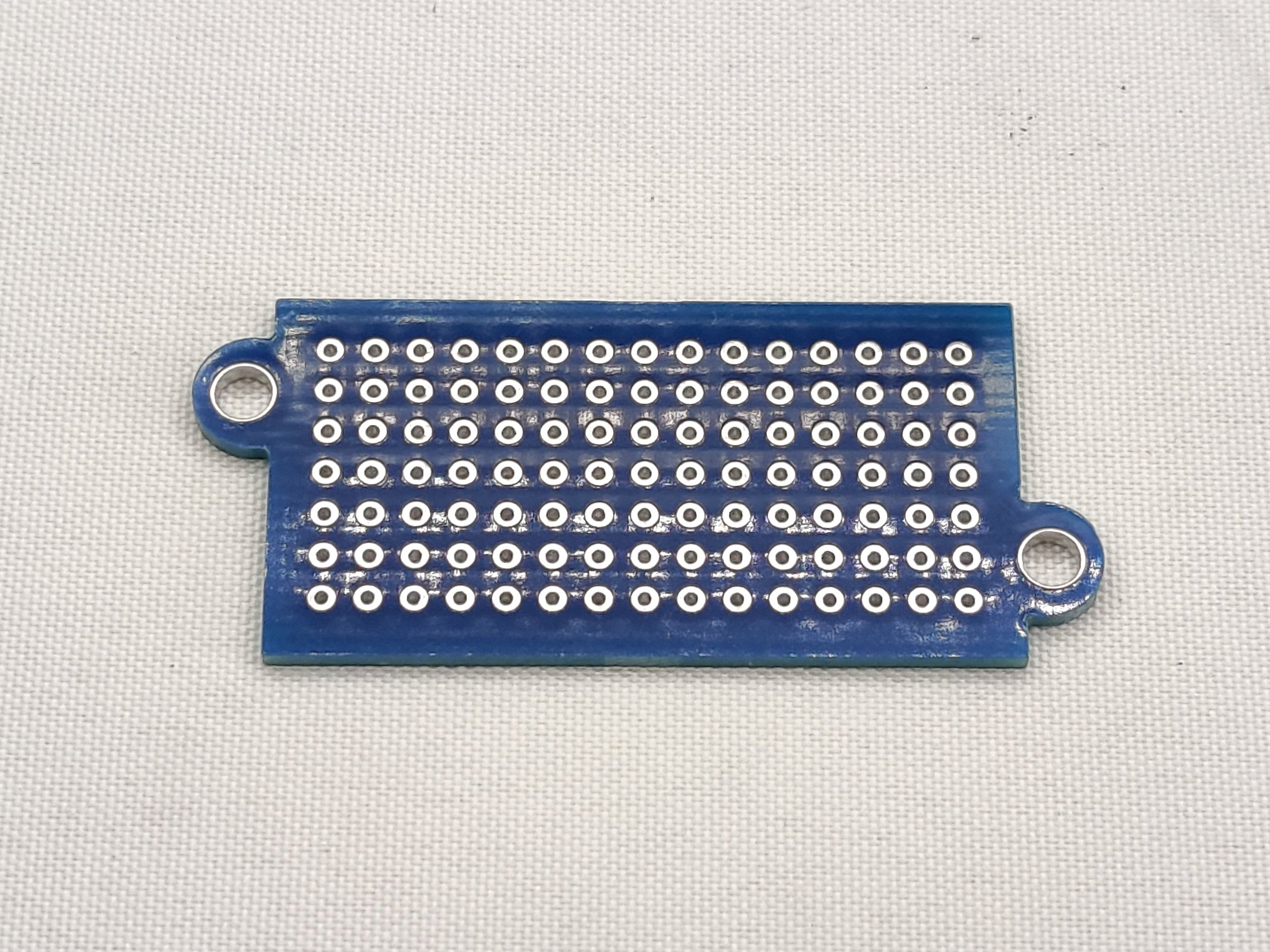
This port cover has 105 solder pads in a 2.54mm (0.1″) grid that have components or connectors soldered to. Ideal for small ancillary circuits or passing through header pins etc.
3D Printed Port Covers
If you have a 3D printer, you can print your own port covers. If you have a Thingiverse account, there is a customisable port cover with a variety of cutouts available. Alternatively, the OpenSCAD code is on the RC2014 GitHub page which you can either select from the predefined cutouts or use that as a basis for your own design.
- Buy the Blue Box Rear Panel on z80kits here https://z80kits.com/shop/blue-box-rear-panel-kit-110x250x190/
- Buy the Port Covers individually on z80kits here https://z80kits.com/shop/rear-panel-port-cover-single/
- Buy the Port Covers 5 pack on z80kits here https://z80kits.com/shop/rear-panel-port-cover/