Assembling the Front Panel I/O Panel is fairly easy, but there are a couple of things which need to be done in the right order for everything to fit together properly. This short walkthrough shows how the Front Panel I/O Panel is assembled in to the Blue Box panel, but the same process would apply if you are using any other enclosure.

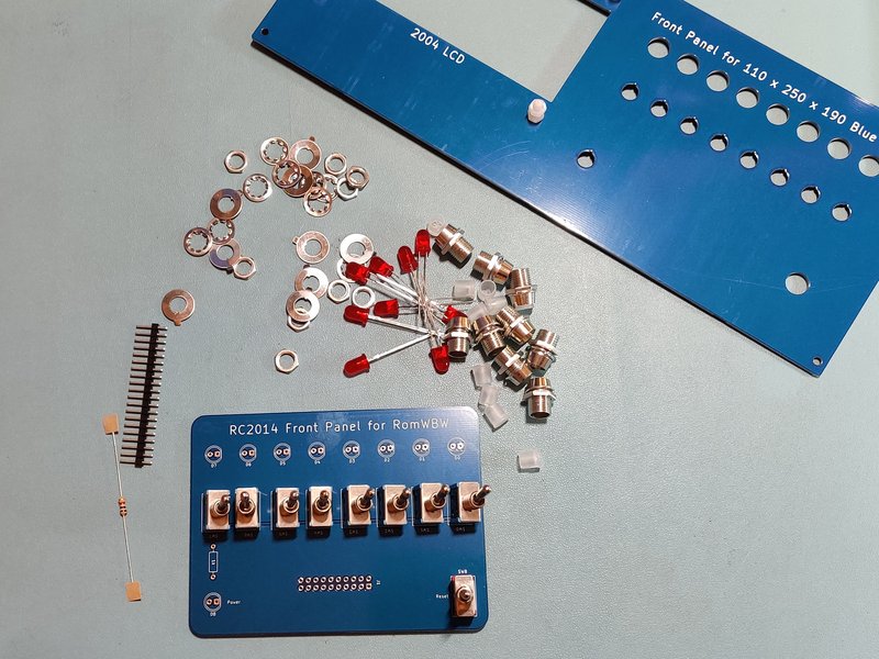
Ensure that you have all the components you need. This is 9 red LEDs, bezels, nuts and plastic spacers, 8 toggle switches with washers and nuts, one momentary switch with washer and nut, a 1k resistor and 20 header pins.
Start by placing all of the toggle switches on the I/O Panel. These go on the side with the silkscreen on them.
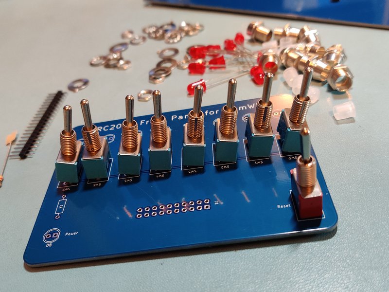
Ensure the toggle switches go in the SW0 – SW7 footprint and the momentary switch goes in the reset footprint. (This should be a different colour to differentiate it). The orientation of the switches does not matter from an electrical or mechanical perspective, as shown above. However, you may wish to align them so that the keyway in the threads all face the same direction for aesthetic and OCD reasons.
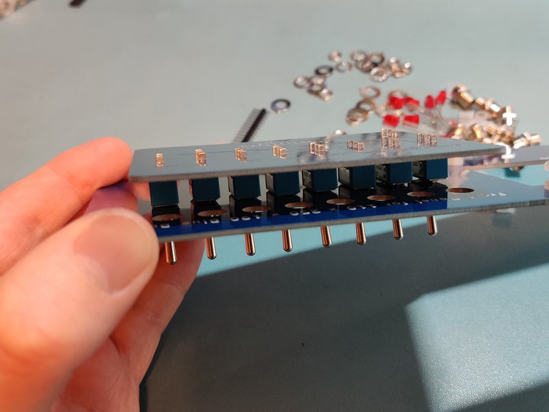
Next place the enclosure front panel over the switches. Everything should align and be snug and straight. When soldering the switches, just solder one pin on each one before returning and doing the second pin on each one, then the third pin on each one to avoid overheating the switch.

Remove the I/O Panel from the enclosure front panel. Add the 1k resistor at this stage.
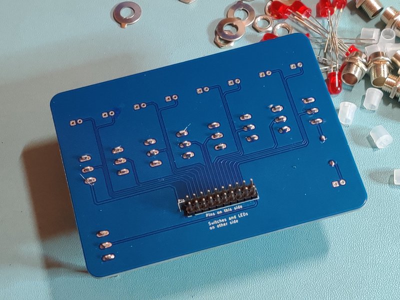
Flip the board over and add the 2 x 10 header pins as shown. (A couple of jumpers can be used to ensure they stay parallel whilst soldering)

Add the plastic spacer on to each of LED. The legs should fit through the two holes with the solid base furthest from the LED, and the tapered top towards it.

Add the bezels to the enclosure front panel, pushing them through from the front.

Fit the washer and nut on the back. A 10mm socket can be used to tighten them.

Fit the LEDs in to the I/O Panel, ensuring the shorter (negative) lead goes through the square hole. Also add the washers to the switches. Then refit the enclosure front panel. This can be fiddly, but with gently pushing one side then the other, making sure nothing has come out of alignment it should go together fine.


Once together, add nuts to the switches and tighten down to hold the panels together.

Panels together, sandwiching the switches and LEDs
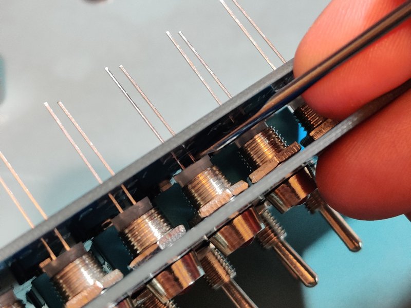
Use a small screwdriver to push down the plastic spacers behind the LEDs to ensure that they are fully inside the bezel.

The LEDs can now be soldered.

Well done! All together. Now simply attach the enclosure panel to the enclosure, fit the ribbon cable and connect that to the Front Panel I/O Module.