The RC2014 Mini II Picasso is exactly the same as the RC2014 Mini II from a schematic and software perspective. Please see the RC2014 Mini II page for full details https://rc2014.co.uk/full-kits/rc2014-mini-ii/
This page covers the differences between the original and the Picasso variation.

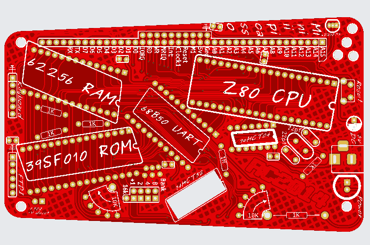
The RC2014 Mini II Picasso is a limited edition kit that is available with a green, white, yellow or red PCB. This PCB has all sockets, mounting holes and pin headers in the same location as the original Mini II, which gives physical compatibility. However, the shape is a trapezoid, which only looks like a rectangle from a certain perspective.
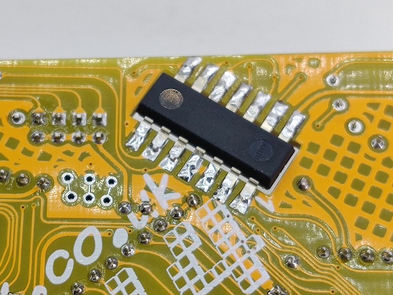
Every single IC is mounted at a different angle to each other and the rest of the components in general. Turned pin sockets are supplied for 5 of the ICs, with the 6th being mounted from below.
The 74HCT32 needs to be modified before fitting. This is the “sunken chip” and will be soldered from the underside. The top side of the chip will be roughly in line with the top of the PCB, and the bottom side slightly below the bottom of the PCB.
Start by bending the legs of the chip out so that they are parallel. This is easiest with two wide flat objects like a couple of rulers, however, wide jaw pliers can be used too. Just try to observe good electrostatic hygiene by keeping yourself grounded or touching ground every so often.
Next trim off the skinny part of the legs close to the wide part.
To solder the chip in place, put a small blob of solder on to the pad for Pin 1. Then lay the chip over the hole and heat up the solder so the leg stump melts in to it.
Check the alignment so that all the legs line up and that the chip is centralised in the hole. Reheating the solder will allow you to adjust this.
Now solder the rest of the pins to the pads.
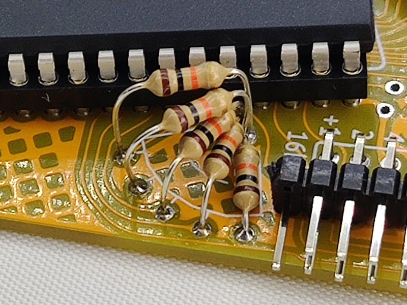
The 10 10k resistors form two 5k spiral resistor staircases. One of these has a common ground hole for all 5 resistors, the other has a common 5v hole for all 5 resistors.
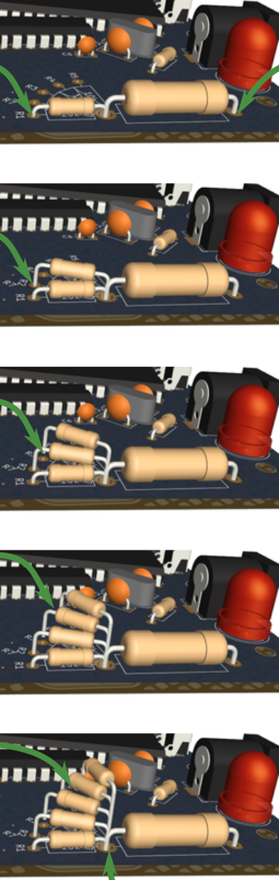
To build the Spiral Resistor Staircase it is easiest to start with the resistor(s) that lie flat on the PCB. However, only solder the end that does not go in to the shared hole.
Experience has shown that it is easiest to solder all these resistors from the top side of the PCB.
Add the second resistor making sure that the end closest to the shared hole is over the top of the first resistor. With the resistor horizontal, solder the end that isn’t in the shared hole.
Repeat this for the rest of the resistors ensuring that they are parallel with the PCB and just soldering the end that isn’t in the shared hole.
With all resistors in place, turn the PCB over and cut the clump of leads in the shared hole almost flush with the PCB. This stump can now be soldered.
Cut the rest of the leads flush and add additional solder if required.
Other changes have been made purely for artistic / aesthetic reasons. For example the 3mm LED on a standard RC2014 Mini has been replaced with an 8mm LED. The 1k resistor that feeds that is rated at 3w. There is absolutely no need for such a high power resistor, and a regular 1/4w would be quite sufficient. Similarly, the reset button does not need to be so long either, but it all adds to the overall effect.
Then there is the track layout. Every pad is a teardrop shape that comes out to a bendy winding track that meanders across the PCB, rarely ever taking the shortest path between two points. The electrons thoroughly enjoy this approach and race each other like BMX racers carrying as much speed as they can over the berms and banked corners.
3 Perspex panels are supplied. The one with the keyhole is the bottom piece and is attached via 10mm threaded hex spacers. The keyhole can be used to wall mount the RC2014 Mini Picasso, either to save on desk space in a messy workshop or to grace the walls of a fine art gallery. Two top layers are supplied. One covers the entire board whilst the other allows access to the 40+10 bus header. Use the latter one if you are fitting any expansion modules. Note that there are only 3 round spacers supplied for the top plate. This is due to insufficient clearance next to the 8mm LED.
Bill of Materials
- 1 RC2014 Mini II Picasso PCB
- 1 40 pin wide turned pin DIL socket
- 1 32 pin wide turned pin DIL socket
- 1 28 pin wide turned pin DIL socket
- 1 24 pin wide turned pin DIL socket
- 1 14 pin narrow turned pin DIL socket
- 1 40 Way random colour SIL Socket
- 1 10 Way random colour SIL socket
- 1 6 Way random colour SIL socket
- 1 6 pin RA header
- 1 2 pin RA header
- 1 5×2 RA header
- 4 jumper (random colour)
- 1 2.1mm random colour power jack
- 1 8mm random colour led
- 1 RA Stupidly Long Tactile Switch
- 1 7.3728 MHz Xtal
- 1 DS1233-5+
- 2 22pf ceramic cap
- 6 100nf
- 4 1k resistor
- 1 1k 3 Watt resistor
- 10 10k resistor
- 1 1M resistor
- 1 74HCT04
- 1 74HCT32
- 1 Z80 CPU
- 1 ST39SF010
- 1 62256 RAM
- 1 MC68B50
- 4 M3 20mm screw
- 4 M3 6mm screw
- 4 M3 10mm hex spacer
- 3 M3 11.1mm spacer
- 1 USB Barrel Lead