The Digital Input Module provides 24 lines of digital input via 3 IO ports. Each port can read 8 inputs, represented by a number between 0 and 255.
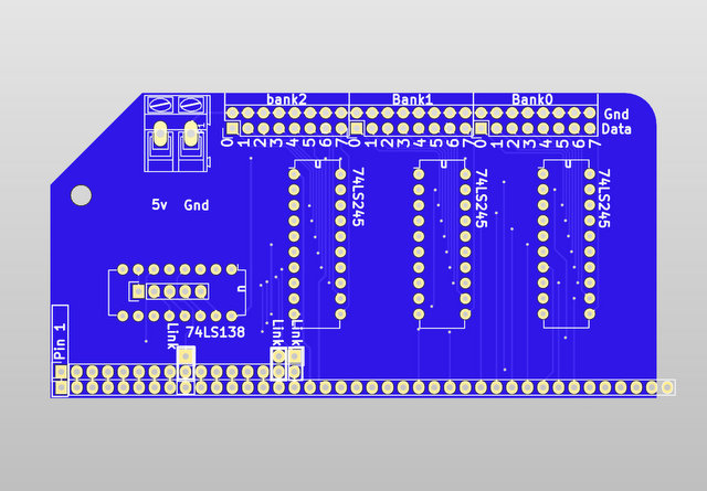
Address lines A0, A1 and !A7 along with M1, IOReq and !WR are used to select the multiplexer 74LS138. This is capable of 8 ports of switching, although for this board, only 3 are used – the other 5 are broken out to pads for further expansion if required.
The address selection pins from the 74LS138 need links to be soldered. It is assumed that A0, A1 and A7 will be used, however, if this clashes with other devices, the other address lines are broken out to be used as required. A0 and A1 provide the addressing when A7 is low, so these 3 ports are nominally 0, 1 and 2 – however, due to the fairly broad addressing scheme, they will respond to any address below 128 that ends with a binary 00, 01 or 10.
For alternative addressing, switching the links to A2 and A3, for example, the ports would respond to addresses of 0b0xxx00xx, 0b0xxx01xx and 0b0xxx10xx. So, port 3, 7, 11 could be used to avoid clashing with the Digital I/O Module
A 74LS245 transceiver is used on each port to read (!Dir connected to ground) the eight lines. These lines would normally be pulled low via resistors and ground pins are provided next to the input pins for this. They can be switched high by connecting them to the 5v pin which is broken out at the top left of the board. When the Chip Enable pin is pulled high, the value of these 8 switches are put on the databus
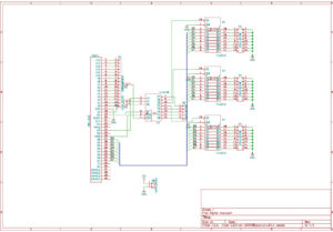
Click image below for schematic in PDF format
In BASIC the port can be read with the INP(n) command which will return a number from 0 to 255 where n is the port number – typically 0, 1 or 2
In assembly language, the mnemonics in a , (n)do the same function
Buy one here
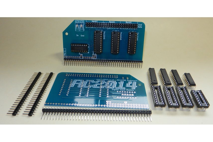
Bill of materials
RC2014 Digital Input PCB 1
40 pin RA header 1
20 pin narrow DIL socket 3
16 pin narrow DIL socket 1
74HCT245 3
74HCT138 1
24 pin header 2