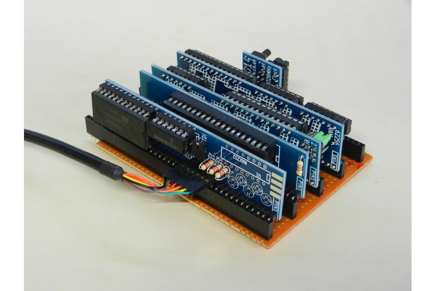
When thinking about a simple but effective back plane / motherboard / bus system, or whatever you want to call it, I kept on coming back to good old stripboard with 0.1″ header sockets on. The PCB is cheap, the interconnects are cheap and it’s ever so versatile and expandable. No need to design another PCB and get tied in to card spacing, just use good old Veroboard and put in as many or as few headers as you want, spaced out where you want.
The layout was pretty much dictated by the pinout of the Z80, with some kind of predictable order added in. Whilst this works pretty well, the only major drawback I’ve come up against is that the supply rails, clock and reset lines are in the middle of the board, so you need to pay attention when plugging the clock/reset board in.
Putting 100nf ceramic capacitors across the +5 and Gnd lines (pins 17 & 18) next to each header socket for decoupling as well as a single 100uf electrolytic somewhere along the +5 and Gnd lines for smoothing is recommended, although I’ve got away with less.
Strictly speaking, you only need 34 rows for the RC2014 to work, however, the Serial IO board puts the Tx and Rx lines on to the bus, so 36 rows is better. However, I recommend 40 row stripboard so that you could carry other voltage rails, video enable or other data signals on the extra pins if needed. (Oh, and the sockets are easier to get hold of with 40 pins – although cutting them down to 34 or 36 isn’t too hard).
| 1 | – | A15 |
| 2 | – | A14 |
| 3 | – | A13 |
| 4 | – | A12 |
| 5 | – | A11 |
| 6 | – | A10 |
| 7 | – | A9 |
| 8 | – | A8 |
| 9 | – | A7 |
| 10 | – | A6 |
| 11 | – | A5 |
| 12 | – | A4 |
| 13 | – | A3 |
| 14 | – | A2 |
| 15 | – | A1 |
| 16 | – | A0 |
| 17 | – | Gnd |
| 18 | – | ‘+5v |
| 19 | – | M1 |
| 20 | – | Reset |
| 21 | – | Clock |
| 22 | – | Int |
| 23 | – | MREQ |
| 24 | – | WE |
| 25 | – | RD |
| 26 | – | IORQ |
| 27 | – | D0 |
| 28 | – | D1 |
| 29 | – | D2 |
| 30 | – | D3 |
| 31 | – | D4 |
| 32 | – | D5 |
| 33 | – | D6 |
| 34 | – | D7 |
| 35 | – | Tx |
| 36 | – | Rx |
| 37 | – | Spare |
| 38 | – | Spare |
| 39 | – | Spare |
| 40 | – | Spare |
To make life a little bit easier, you can print off This PDF on to an adhesive label sheet and stick it to the top (non-copper) side of your back plane to see which rows carry which signals. Print it with no scaling to A4 paper and it should fit perfectly. If you stick it to the PCB before putting the headers or capacitors in and simply poke the pins through. Alternatively, cut it in to thin strips in-between the headers if you’ve already soldered them in. The original .ods sheet is attached if you wish to modify it.