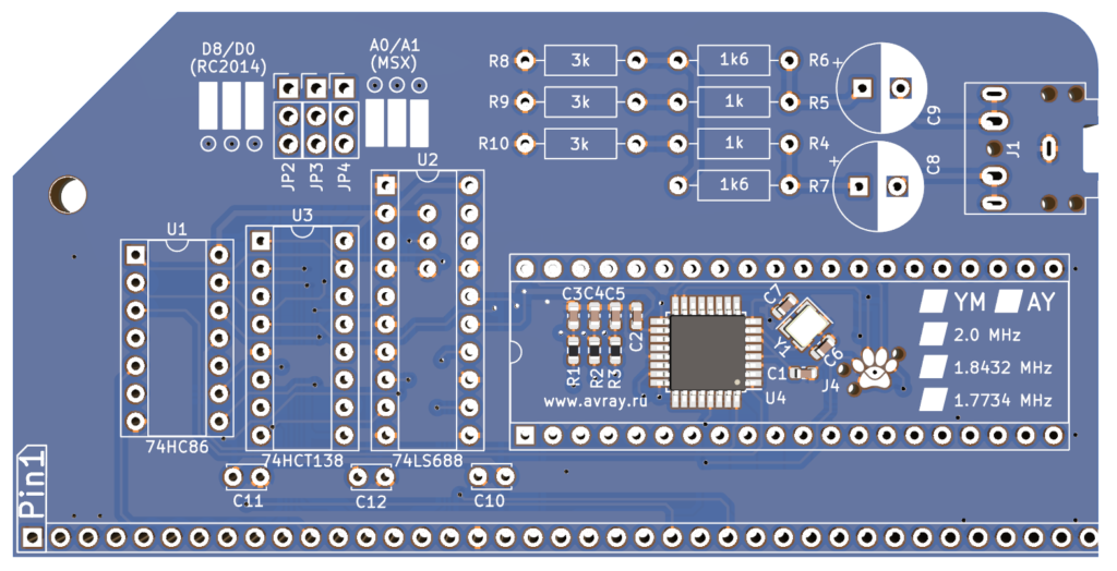
The Why Em-Ulator Sound Module is a sound card for the RC2014 based around the AVR-AY emulator. This firmware can be programmed to emulate either a YM2149 or an AY-3-8910 / AY-3-8912 classic sound chip. A simplified addressing system allows the module to use the standard RC2014 ports (D8/D0) or MSX ports (A0/A1). The pre-soldered SMD components can be disguised with an optional DIP40 IC. Audio output is via a 3.5mm headphone jack.

This module simplifies the addressing scheme of Ed Brindleys YM2149 Sound Card whilst also using an ATMega48 to emulate an AY or YM chip. This has the benefit of not relying on hardware that went out of production decades ago.
Click image to open PDF schematic

Assembly
Assembly is pretty straightforward, and similar to most other RC2014 modules. Start with the lowest components and work your way up. The ICs and IC sockets have a notch in one end which should line up with the silkscreen. The large electrolytic capacitors should also be lined up so the white stripe aligns with the white marking on the PCB.
The 40 pin DIP socket is optional. You can use this to mount a dummy chip to hide the surface mount components. None of the pins are connected to anything, so no damage will be caused to either the chip or the components. This is a great place to mount a non-functional YM2149, but any chip can be used. Why not use a 6502 and prank your friends!
Hardware
The addressing is done by two chips. Firstly the ’86 XORs A6 with A5 and also A6 with A4. This means that the 010 and 101 pattern formed in the port address A0/A1 and D8/D0 can be identified. (It will also identify ports 50/51 and 20/21 too. More on that later). An ‘866 comparitor is then used to look at A7, A2, A1, M1 and IORQ. If these match the levels on the other side of the ‘866 then the ‘138 !E0 will be enabled. !E1 is tied to ground, thus already enabled. And E2 is enabled by either A4 or A5. This will determine if the D8/D0 or A0/A1 addressing is used. The output of the ‘138 is determined by address A0, A3 and also the !WR line. This logic will give 4 possible outputs, of which 3 are used to drive the BC1 and BDIR signals on the YM2149. Because the D0 port is needed for BDIR but also A0 port is needed for BC1 and vice versa, two jumpers are used to swap these around.
The emulation is done by an ATMega48 with the same circuit as used by Yevgeniy Olexandrenko that will run the AVR-AY firmware. Essentially this is a microcontroller with minimal support componets, connected to the data bus, the BC1 and BDIR signals, and 3 outputs for Channel A, Channel B and Channel C. A 6 pin TC2030 compatible programming header is also used.
The audio channels go in to a simple mixer which gives the golden ratio for 2 channel stereo output via two capacitors.
Port 20/21 50/51 hack
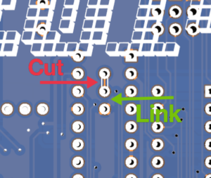
The Colecovision uses port 50/51 and some people also use port 20/21 for the PSG. Luckily these addresses cover the same binary pattern as the A0/A1 and D8/D1 addresses except for the bit on A7. This means that setting A7 low on the comparitor instead of high is an easy hack. To make it easier, there is a cuttable link under the ‘688. Simply cut the PCB track where shown and solder a link between the lower two pads.

Firmware
The firmware used on the micro is from AVR-AY and can be found here https://www.avray.ru/ There are various builds of this and different config files depending what ATMega is used, what crystal it has, what crystal it emulates being driven by, and if it is a YM or AY chip. The source code is there too if you want to make any particular tweaks. The firmware used on this module by default is AY_Emul_260_3ch_m48_ym_speaker.hex with Conf_parallel_27MHz_1_78Mhz.hex configuration file.
Software
The Why Em-Ulator Sound Module can be programmed in BASIC, Z80 Assembly, FORTH, or indeed any language that can output a value to a port. PLAYER.COM which can play .PT2 and .PT3 files and is available for CP/M. RomWBW includes it, along with some PT3 files too. PLAYER YEOVIL.PT3 for example will play Through Yeovil, a great chiptune by Gasman. The following BASIC program should get you started, although you may need to consult the YM2149 or AY-3-8910 datasheets to understand what registers are used for what purposes.
10 R=216 : REM 0xD8 - Register
20 D=208 : REM 0xD0 - Data
30 OUT R,7 : OUT D,62 : REM Set mixer register to enable Channel A only
40 OUT R,8 : OUT D,15 : REM Set Channel A volume to max
50 FOR N=1 TO 255
60 OUT R,0 : OUT D,N : REM Set pitch of Channel A too N
70 OUT 0,N : REM Output to Digital I/O LEDs too
80 GOSUB 100
90 NEXT N
99 OUT R,7 : OUT D,63 : REM Turn off sound
100 FOR X=1 TO 64 : NEXT X : RETURN
Bill of materials
1 RC2014 Why Em-Ulator PCB
1 40 pin RA header
1 14 pin narrow DIL socket
1 16 pin narrow DIL socket
1 20 pin narrow DIL socket
1 40 pin wide DIL socket
1 74HCT86
1 74HCT138
1 74HCT688
3 100nf
3 3 pin header
3 jumper
2 1k resistor metal
2 1k6 resistor metal
3 3k resistor metal
2 47uf 25v electrolytic
1 3.5mm headphone socket
Sound Samples
Writing about a sound module is all well and good, but a tune can paint a thousand words. Below are versions of the same track played by the AVR-AY emulator with different settings as well as with original YM2149 and AY-3-8912 chips. By default the emulator is shipped out to be a YM2149 clocked at 1.7734MHz. If you have a preference, this can be programmed as an AY-3-8910 or with a different speed. To help you decide, and to compare it to the original chips, please have a listen to the options below.
Bonus Track
Through Yeovil was written by Gasman and used with permission.
Misirlou is a traditional song arranged for the YM2149 by Shiela Dixon for use in the RC2014 port of Tut-Tut and used with permission.
The tracks above were recorded as WAV files directly from the sound card using a Zoom H1n recorder. Other than trimming to length in Audacity and exporting as MP3, no other processing or tweaking has been done.

