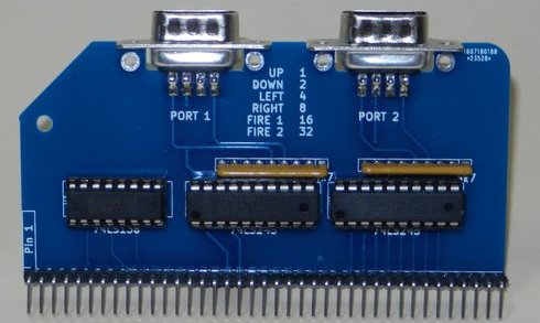
The Twin Port Joystick Module allows the RC2014 to take input from 2 “Atari” style joysticks.
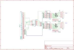
This board is essentially a variation of the Digital Input Module, with port 1 and 2 being wired to two 9 pin D sockets. Resistor arrays hold the inputs low unless the joystick is pushed up, down, left, right or either of 2 fire buttons are pushed.
A Snake game, available on GitHub, is one example of a game that can make use of joystick port 1 – however, reading the joystick port for use in other programs is very simple.
In BASIC the port can be read with the INP(n) command which will return a number from 0 to 63 where n is the port number 1 or 2.
- Up – 1
- Down – 2
- Left – 4
- Right – 8
- Fire 1 – 16
- Fire 2 – 32
Other numbers represent a combination of these. For example, 18 would be returned when Down and Fire 1 are both pushed.
In assembly language, the mnemonics in a , (n)do the same function
Buy one here
Bill of materials
RC2014 Joystick PCB 1
40 pin RA header 1
20 pin narrow DIL socket 2
16 pin narrow DIL socket 1
74HCT245 2
4k7 Resistor Pack 2
74HCT138 1
9 pin D socket 2