When I failed to complete the Retro Challenge in 2016 I finished by saying that the dog ate my homework. That sounded like a reasonable enough excuse.
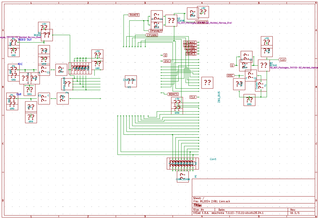
This year any failure to complete is because The Riddler ate my schematic!
One of the first things I wanted to do was familiarise myself with what 2016-me did regarding the ZX81 module I designed for the RC2014. I have 3 PCBs here, and whilst they look great, they lack some info, such as the component values. So I opened up the schematic I created and discovered that all of the components have been replaced by ?? boxes!
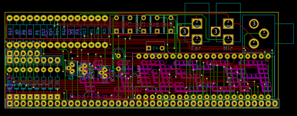
To be fair, this isn’t the first time I have seen this situation. This was probably created in Kicad v4 or possibly earlier, and one thing which Kicad was terrible with back then was keeping track of component libraries whenever there was an upgrade. I am now using Kicad v8, so there have been a lot of upgrades.
I might be able to install a fresh copy of an old version and hope that has the right libraries and I can map them in to work with the schematic. I think that most of the components are resistors and capacitors though, so even if that worked, I wouldn’t have the values anyway.
I think it will actually be easier to convert the schematic to the v8 standard and manually change each of the parts to the resistor, capacitor or diode as approprite. I still won’t have the values, but the thing I do have is the original ZX81 schematic that this module was based on, so it should be a case of matching things up.
Mid-blog update
I looked back at the intro post that I made and noticed that the photo I reused from 2016 was a picture of the partially assembled module that was sitting on a schematic printout. The values can be seen too!
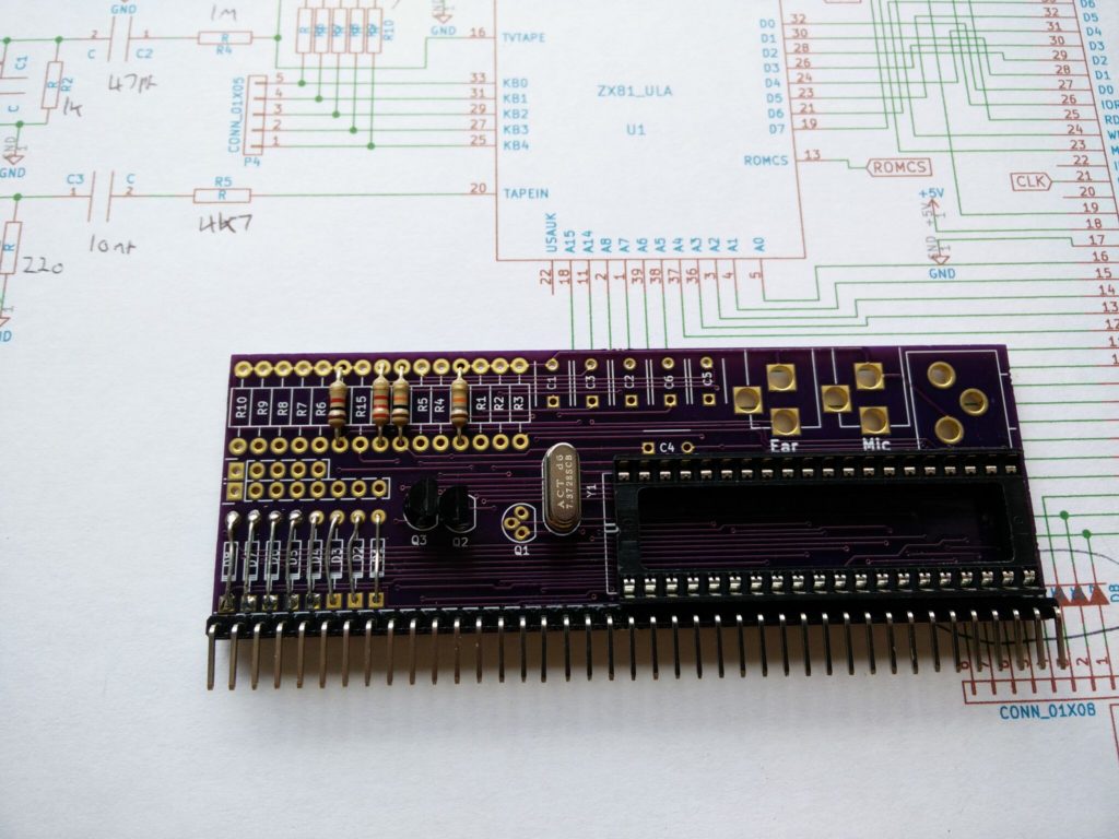
So that makes life easier!
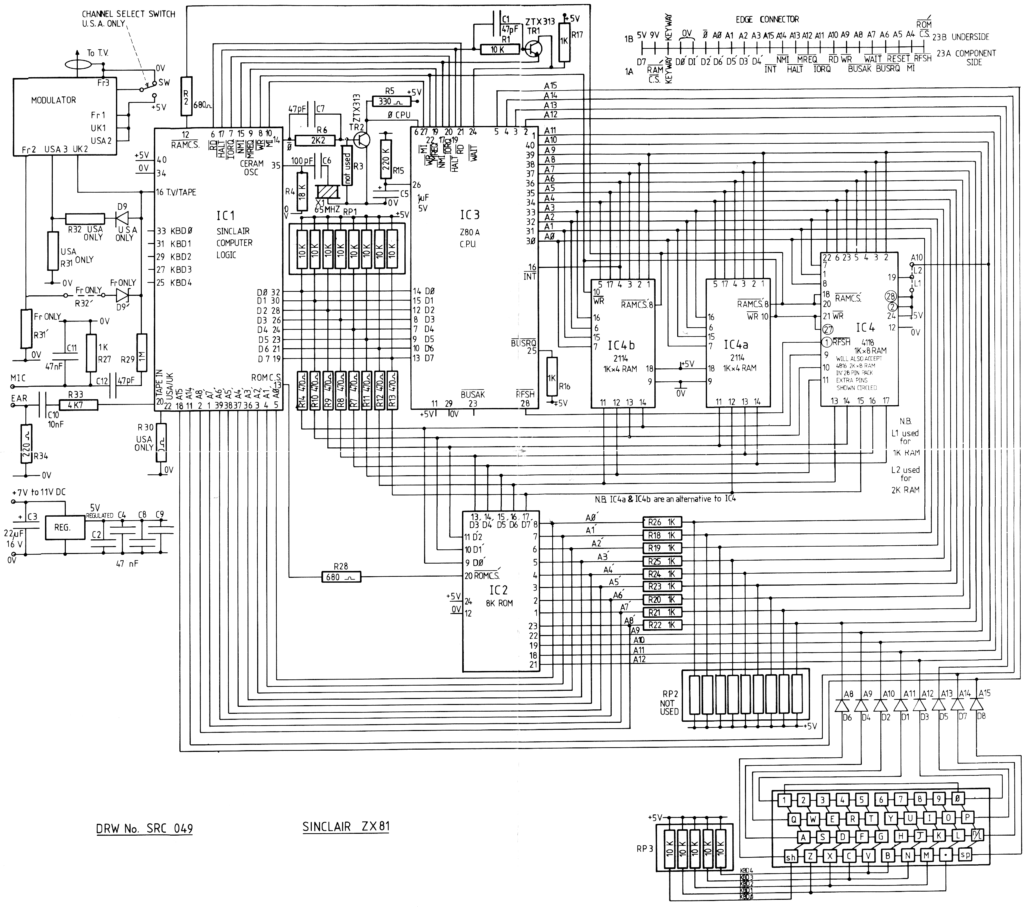
Not only that, but another blog post from 2016 also has the full schematic (less component values) so that helps too!
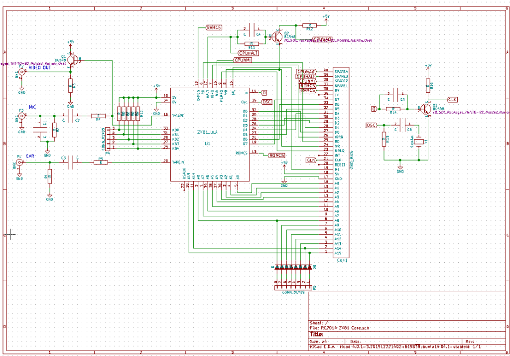
The RC2014 has come along way since this module was conceived 8 years ago. I think some of the stuff that I had learned about the ZX81 back then had guided some of the decisions that I made later, which actually helps this a lot.
Firstly, the Backplane 8 and Backplane Pro both have the ability to add resistors on the data and address bus, as the ZX81 did. There is now an RC2014 keyboard which mimics the ZX81 or Spectrum layout and has the diodes onboard, so that makes things easier too. The Pageable ROM module supports 16k blocks, which will help if anything on the ZX81 needs to access the shadow ROM in 0x2000 – 0x3FFF. And, lastly, the 64k RAM module can be set to start at any address. With the ZX81 having RAM mapped from 0x4000 – 0x8000 this is perfect.
