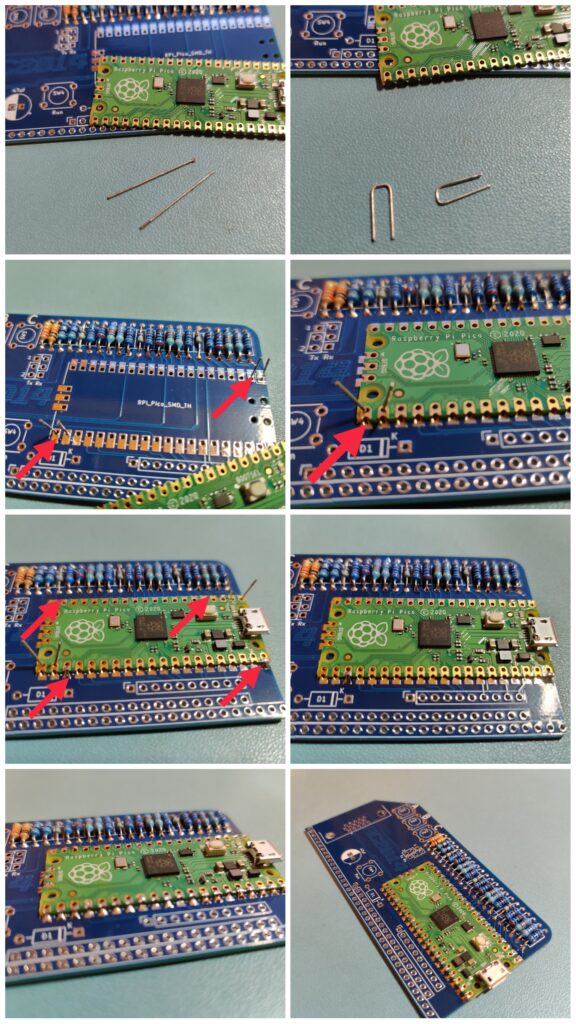
If you haven’t soldered surface mount modules before, the Raspberry Pi Pico supplied with the Pi Pico VGA Terminal might look a bit challenging. Like most things, if you know what you’re doing, it is actually pretty easy. Here’s the method I use;
Take a couple of resistor lead off-cuts
Bend in to a staple shape about 2.54mm (0.1″) wide
Poke these staples through from the underside of the PCB in opposite corners
Bend them apart slightly to keep everything lined up
Solder opposite corners and a couple of other pads to keep things in place (Do NOT solder the pads with the staple though).
Having finished the first section of the Zero to ASIC course, I think it’s fair to say that I know a lot more about MOSFETs than I thought I ever would. MOSFETs are the building blocks of digital logic, so it is important to have a good grasp on why they are used, how they work, and how they are made.
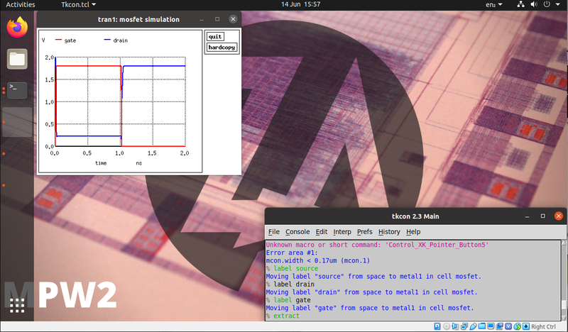
Zero to ASIC virtual machine running Magic and Spice on Ubuntu
There are several software packages and toolchains used for this course, and whilst they can all be downloaded and run locally on your own machine, I opted to download the virtual machine which has everything installed and configured. This lets me focus on the course itself rather than worry about installing the right version or having different settings. It also means I can swap between my laptop and desktop machine easily. Each section of the course has a GitHub repo to clone which includes examples and makefiles to do some of the heavy lifting.
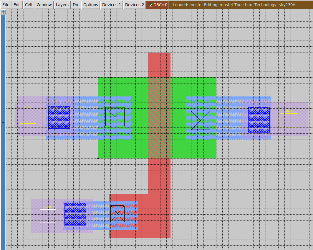
MOSFET construction using Magic VLSI tool
One of the pieces of software was a VLSI tool called Magic. Using this I was able to create a MOSFET by laying down layers of N diffusion, polysilicon, and metal interconnects and use the appropriate interconnects to join them all together. This was then exported so that it could be simulated in Spice to see how well it performed.
Although it would be possible to design my entire silicon project by drawing every single MOSFET by hand, luckily that isn’t necessary.
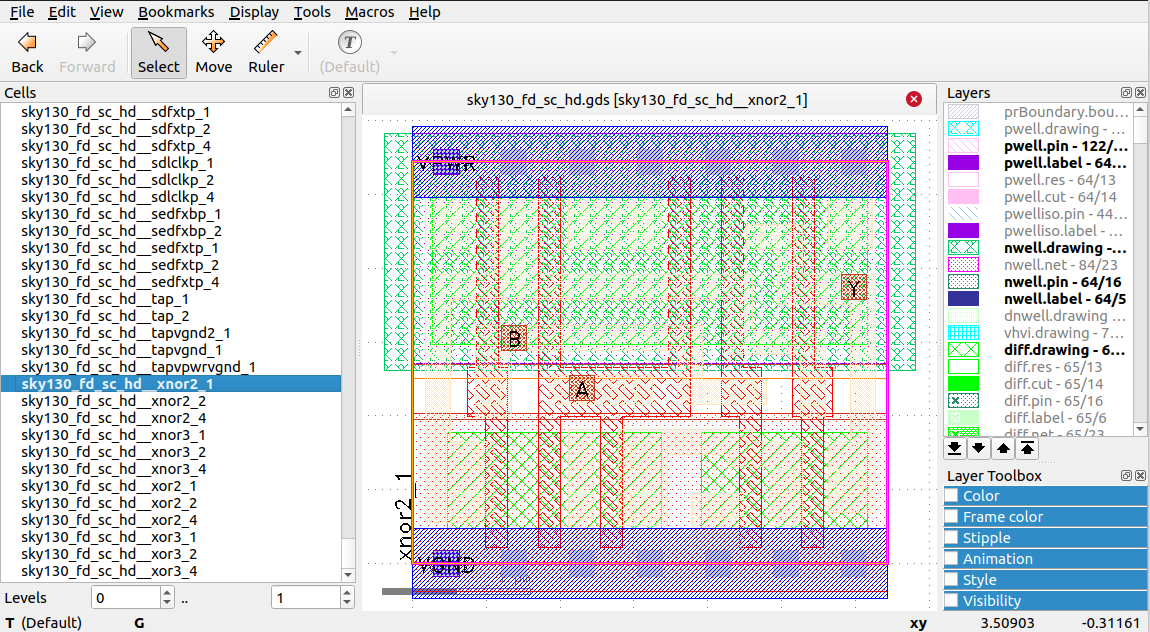
KLayout library
KLayout has a library of hundreds of different standard cells which can be used. This includes all the basic logic functions you’d expect as well as buffers, flipflops and other parts which I haven’t got a clue what they do!
I focused on a 2 input XOR gate. Again, though the use of Makefile scripts, I could export this part and run it through Spice to assess its performance.
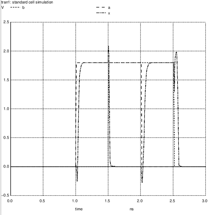
Spice simulation of XOR gate
The parameters in the Spice configuration generates an offset pulse on the A and B inputs and plots a graph of the inputs and outputs based against time. Being an XOR gate, it is hardly surprising that the output is high when either A or B is high, but low when they are both high or both low. What was surprising, however, was the detail in the output, including the under/overshoot and the propagation delay. Whilst this might seem trivial on a simple gate like this, chaining hundreds of them together on the same piece of silicon you can see how that all adds up.
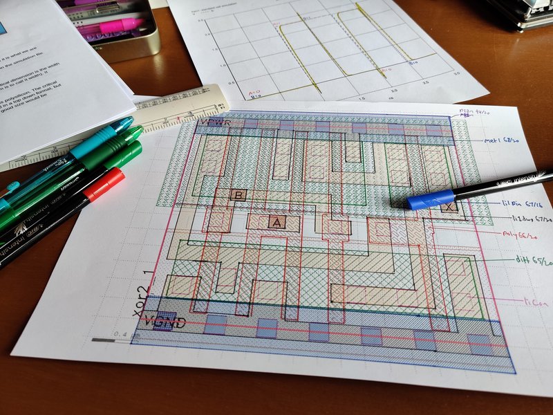
Reverse engineering XOR silicon
This is where I started to go down a rabbit hole. An XOR gate is, comparatively speaking, a simple device, only made up of a few MOSFETs and interconnects. I knew what a MOSFET looked like, so I decided to reverse engineer this so I could produce a schematic of it, and build it out of through hole components on a breadboard. For size comparison, this square of silicon is 0.0032mm on each side. Each leg on the through hole MOSFETs I have are approx 0.3mm wide.
Sadly, reverse engineering this proved to be a step too far for me. Whilst I could identify several MOSFETs with 100% certainty, things were not lining up with any of the XOR circuit diagrams I had already found. This is, however, well beyond the scope of this course though, and not something which should be necessary to end up with my own custom chip. It is something which I would like to come back to at a later date though, as I can see skills here being useful for other projects.
A few weeks ago I was given the opportunity to sign up for the Zero to ASIC course offered by Matthew Venn. This is a really exciting prospect as it is not every day that you get to design your own custom silicon! I had always though of chip design as one of those things that only big corporations filled with academics could do, which is the same way that I though of designing and building computers until a few years ago. Looking through the syllabus for the course, though, it certainly looks like it is within reach for mere mortals like myself. At the end of it I can submit my design, and if I am lucky, I will end up with a few pieces of silicon with my own circuit on it.
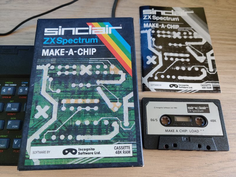
Make-A-Chip software for ZX Spectrum
I will be updating this blog as I make my way through the course, highlighting anything of interest, or bits I struggle with, or giving some details about some of the choices I make. There will also be a series of interviews on YouTube after each section of the course where we discuss how things are going, what I’ve learned and maybe other stuff. The first episode is available on YouTube now;
So, the important question is what am I going to make? When the possibilities are almost endless, I had to narrow things down. I decided that I wanted to design something which I understood well enough to make out of 7400 series logic (So full CPU design is out), something that wasn’t just an off the shelf part (no point making just another RAM chip), and something which would benefit from the tiny size that this will give.
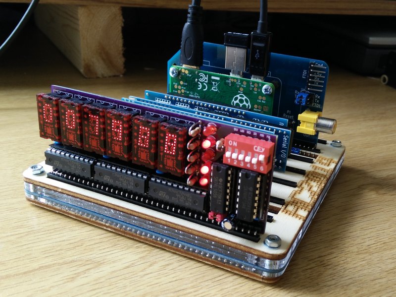
TIL311 Displays in a RC2014 Module
A few years ago I built the Bus Monitor board designed by Dr Scott M Baker. This uses the iconic TIL311 hexadecimal LED displays. These are absolutely beautiful, and also really easy to use as each display has the decoding on board to convert 4 bits of the bus to a 0-F hex display. They were very popular in the 1970s and used in all kinds of equipment. They have only two drawbacks as far as I can tell; they are very power hungry, being based on early LED technology, and they are rare/expensive as they were discontinued decades ago.
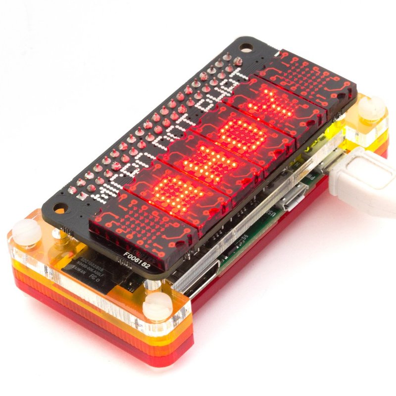
Microdot PHAT by Pimoroni
There is no direct equivalent available today. But there is, however, a LED matrix by Lite-On called the LTP-305. This has the aesthetic beauty of the TIL311, and is much more power efficient too. Sadly, though, this is just a simple 5×7 LED matrix so displaying the characters for 0-F from 4 bit input needs quite a bit of circuitry to drive it.
I have thought about this several times in the past, and making the logic needed to run a pair of LTP305 is going to be huge if using 7400 series DIP logic chips. It will be much smaller with an FPGA, although it would need some level shifters as the RC2014 bus runs at 5v and almost all FPGA have 3v3 (or lower) I/O pins.
But, what if there was a piece of silicon just a couple of mm square that could be on a PCB the same size as a couple of these displays, transforming them in to a plug in replacement for the TIL311? Wouldn’t that be cool? If you think so, then keep on checking in on this blog over the next few months to see how things are coming on.
Oh, and to answer some of the obvious questions, yes, I am fully aware that this proposed design will work out to be much more rare and much more expensive than the TIL311 displays. Which I already have. This is not about solving that part of the problem. If I just used TIL311 displays then I wouldn’t learn anything about ASIC design!
Yes, I am also aware of the Pixie boards from Lixie Labs. These solve a diferent problem, but are not what I am looking to do here. I also know about ReTIL too, which is solving basically the same problem but in a very different (and very cool) way.