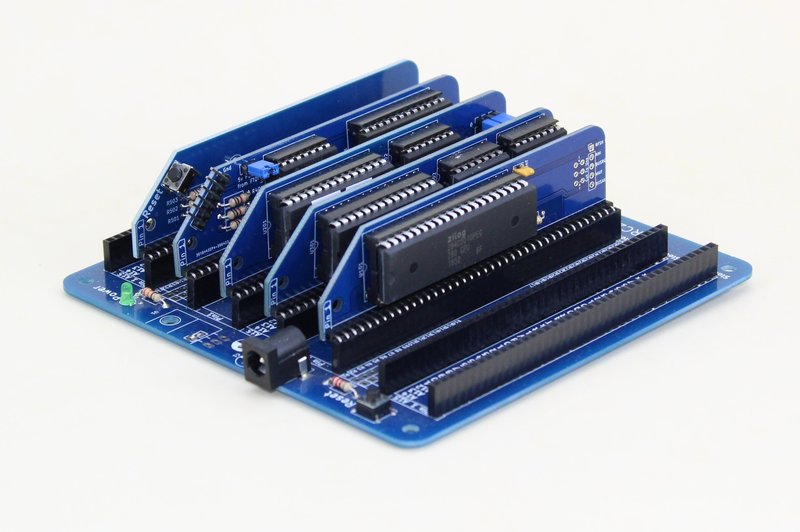
The RC2014 Classic ][ is a followup to the RC2014 Classic. It is a modular Z80 based computer kit. 5 modules, the CPU, ROM, RAM, Serial I/O and Clock/Reset are mounted on a passive backplane.

The assembly guide for the Classic ][ can be found here
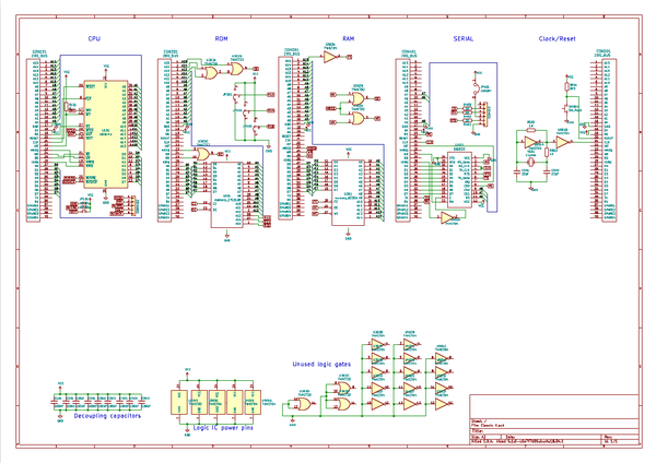
The full pdf schematic for the Classic ][ can be found here
Z80 CPU
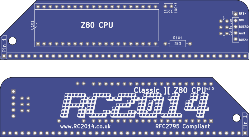
The Z80 CPU board is the most simple of all the modules. All 16 address lines, 8 data lines as well as the M1, Reset, Clock, INT, MREQ, WR, RD and IORQ are all presented to the RC2014 expansion bus. INT is pulled high with a 3k3 resistor.
WAIT, NMI, BUSRQ, BUSAK and RFSH signals are not needed for normal operation in the Classic ][. However, they are bought out to a 6 pin header if you have a requirement to use them. Note that WAIT, NMI and BUSRQ are all pulled high to 5v. If you wish to drive these lines externally, you must cut the tracks where marked. (A jumper can be fitted if you cut the track and no longer want to control it externally).
Bill of Materials
1 Classic II CPU PCB
1 40 pin RA header
1 40 pin wide DIL socket
1 Z80 CPU
1 3k3 resistor
1 100nf
Banked ROM
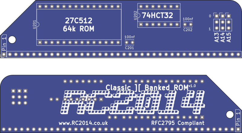
The Banked ROM takes a 27C512 OTP ROM. This 64k ROM only has address lines A0 to A12 connected to the bus (ie only 8k is visible to the RC2014 bus). Address lines A13, A14 and A15 from the ROM are bought out to 3 rows of header pins. Setting these 3 address lines high or low determines which 8k bank of the ROM is currently accessible. Setting all 3 low will select the lowest bank.
Address lines A13, A14 and A15 from the RC2014 bus must all be low for the Chip Enable pin to be active. This defines the ROM area being 0x0000 – 0x1FFF. If the RD and MREQ lines are also low, then the Output Enable pin is active, and the ROM will put data on to the data bus based on what address A0 – A12 are active.
The ROM supplied with the Classic II is labelled R0000009. This indicates that 32k BASIC (R) is in the first 8k bank (selectable by setting all 3 jumpers low). SCM, Z80 Monitor ROM (9) is in the highest 8k bank (selectable by setting all 3 jumpers high). The middle 6 8k banks are all unprogrammed, therefore will not do anything if selected. However, if you have an EPROM programmer, these can be used as required.
Bill of Materials
1 Classic II ROM PCB
1 40 pin RA header
3 3 pin header
1 28 pin wide DIL socket
1 14 pin narrow DIL socket
1 27C512 EPROM BASIC
1 74HCT32
2 100nf
3 jumper
32k RAM
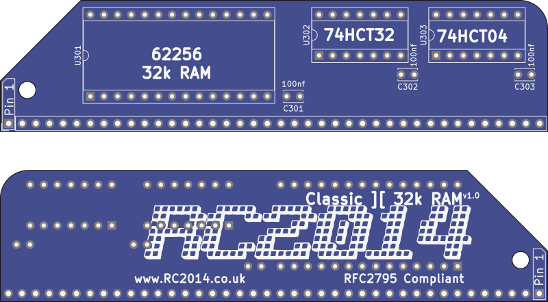
A single 62256 Static RAM chip provides 32K of memory to the Z80. Address line A15 goes through a NOT gate on a 74HCT04 to the /CE pin, thus mapping this memory to address 0x8000 – 0xFFFF. The /WE and /OE lines are controlled by ORing the /MREQ with the /WR or /RD from the Z80
Bill of Materials
1 Classic II RAM PCB
1 40 pin RA header
1 28 pin wide DIL socket
2 14 pin narrow DIL socket
1 62256 RAM
1 74HCT04
1 74HCT32
3 100nf
Serial I/O
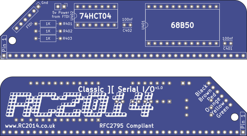
A MC68B50 Asynchronous Communications Interface Adapter (ACIA) gives the RC2014 the ability to talk to the outside world through a serial port.
Address A0, A6 and A7 put the 68B50 on port 0x80 and 0x81. When these addresses are selected, along with IORQ and M1, the chip is active, and will read or write depending on the state of the WR signal. The IORQ pin from the 68B50 goes back to the INT pin on the Z80 so it can trigger an interrupt when it has data in its input buffer.
The 68B50 is run from the same clock as the Z80, which with a 7.3728Mhz crystal will communicate at 115200 baud. (If a 3.6864 Mhz crystal was used, the baudrate drops to 57600, and so on)
If the RC2014 is being powered from an FTDI lead, then the “5v Power From FTDI” jumper should be in place. Otherwise, remove it. Note that with just the bare essentials (CPU, ROM, RAM, Serial I/O and Clock), the RC2014 pulls around 200ma, which is well within the 350ma or so that most FTDI leads can supply.
Both the Tx and Rx lines are presented on the pins to the back plane (Pins 35 & 36), so building additional interfaces to communicate with this is straight forward.
This board is designed to be used with a 5v FTDI lead. The official colours are;
- Black GND
- Brown CTS
- Red VCC
- Orange TXD
- Yellow RXD
- Green CTS
Most 3rd party serial to USB cables use the same colour scheme, but if your cable or adapter doesn’t use this, match things up by the pin signal.
Clock and Reset
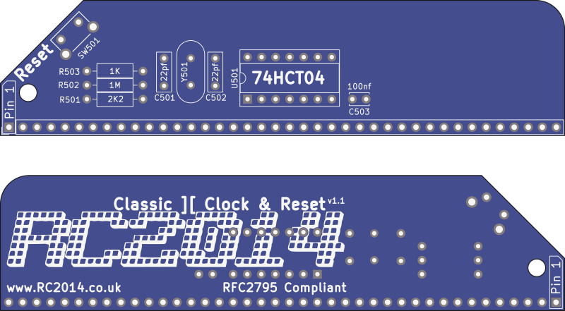
The clock uses a 7.3728 MHz crystal with a couple of inverters to generate a square-ish wave form. This runs both the Z80 and the 68B50 UART.
The reset line is pulled high through a 2k2 resistor, and will go low when the button is pushed. The reset circuit is the same as on the backplane, so that it can also be used on a backplane without a reset circuit.
Backplane 8
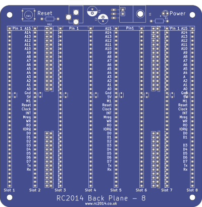
The backplane ties all the modules together, and allows for extra modules to be added. The only circuitry on the backplane is a reset circuit, which duplicates the reset circuit on the Clock And Reset Module, a power LED, and an optional 5v regulator circuit.
It is expected that the RC2014 will be powered from either the FTDI cable, or through a 5v barrel jack connection, in which case, simply solder a wire link across the “5v direct” pads. If you wish to use a higher powered adapter, then a LM7805 or equivalent and two capacitors must be fitted. Note that 7805 devices are very inefficient, and can get very warm, so it is worth checking out pin compatible switch mode regulator alternatives.
The backplane itself is essentially glorified stripboard, and simply connects each pin of slot to the same pin of the others. Between Slot 2 & 3 and also Slot 6 & 7, however, there is a break in the data and address lines. This gives you the ability to run some modules isolated, add limiting resistors, or to ‘re-plum’ the address lines to change what address a peripheral is accessed on. If you are new to the RC2014 world, however, it is unlikely that you will need to do this, so to fully utilise slots outside of Slot 3 – Slot 6, the pads must be bridged. See this guide on a quick and easy way to lace them up.
Whilst the order of the modules makes no difference, it is recommended to put the CPU, ROM, RAM, Serial, Clock in to Slot 3 – Slot 7 respectively. (Note that the Clock module only uses power, Reset and Clock signals, and can therefor go outside the main block without needed additional links being soldered). Pin 1 of the modules should line up with Pin 1 of the slots.
If you are powering the bakcplane from the barrel jack, you should remove the 5v jumper on the Serial I/O Module.
Software
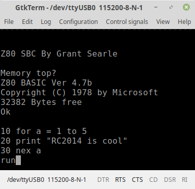
The RC2014 Classic ][ comes with Microsoft BASIC and SCM on ROM. Setting the jumpers on the ROM Module will determine which of these boots when the RC2014 is powered on.
Microsoft BASIC was used by many computers in the late 70s and early 80s, including TRS80, Apple II, Commodore PET, VIC-20, C64, IBM PC Jr etc. The particular variant supplied with the RC2014 Classic ][ is derived from the NASCOM 2, with modifications by Grant Searle. These modifications essentially remove commands that relate to NASCOM 2 specific hardware and also adds commands to deal with Hex or Binary numbers. For more information see the manual for NASCOM 2 BASIC and Grant Searles modifications
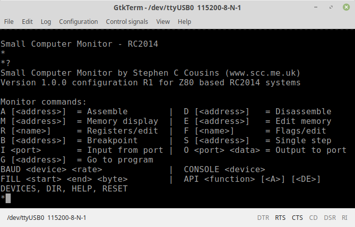
Small Computer Monitor, or SCM, is a Z80 monitor ROM which allows you low level access to the RC2014. This includes assembling and disassembling Z80 assembly code, direct port access, memory manipulation, as well as single stepping through code, examining registers and setting break points. It also features the ability to load Intel .hex files in to memory. Information on SCM can be found here, and the tutorial is highly recommended.
Using The RC2014 Classic ][
Before powering on your RC2014 for the first time, take a moment to double check all solder joints for solder bridges, dry joints, or missed joints. Ensure all components are orientated the right way and chips are pressed in firmly. Set the jumpers on the ROM Module for either BASIC or SCM and install all modules in to the backplane. If you are powering the RC2014 from the barrel jack, ensure the 5v jumper on the Serial I/O Module is removed. Alternatively, if you are powering it from the FTDI cable, ensure that jumper is fitted.
Connect your FTDI cable to your computers USB port, and fire up your favourite terminal emulator. (If you don’t have a favourite terminal emulator, then TeraTerm for Windows, GtkTerm for Linux, or MiniCom for Mac are recommended). Ensure that your terminal emulator is using the serial port that your FTDI device shows up as, and is set to 115200 baud, 8 bits, No Parity, 1 Stop Bit (8-N-1 is the default on most devices). Connect the FTDI header to the RC2014, in accordance with the colour pinout as described above, and hit the reset button. You should then be greeted with the welcome message for either BASIC or SCM.
If booting to BASIC for the first time, it will ask for Memory Top? Just hit return here for the full 32k to be available. Subsequent resets will ask for Cold or Warm start. Cold clears the memory before starting, Warm retains whatever was in memory before the reset. You’re then ready to start programming in BASIC!
If booting to SCM you will be greeted with a welcome message and a * prompt. Hit ? [return] for a summary of commands. You’re then ready to start programming in Z80 assembly language!
Troubleshooting
If your RC2014 Classic ][ fails to boot up, don’t worry. Most faults can be traced visually, and few faults lead to permanent damage. All the chips should be cool to the touch, though, so if it is not booting and one of them is getting hot, remove the power quickly!
Read through the Troubleshooting Guide here for pointers on what to look out for. If you are still having issues, use the Contact me link, or visit the RC2014-Z80 Google Group. Be prepared to explain exactly what the issue is, and what steps you have already taken. It may help to provide clear photos of the assembled boards too.