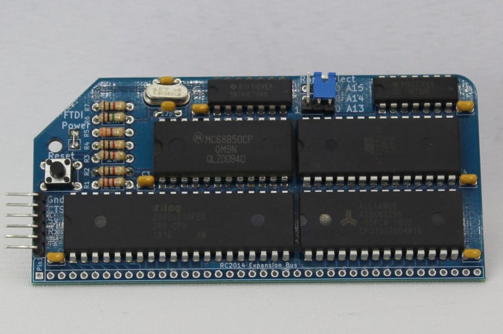
The RC2014 Micro is a 32k Z80 based single board computer which runs either Microsoft BASIC or Steve Cousins SCM monitor ROM.
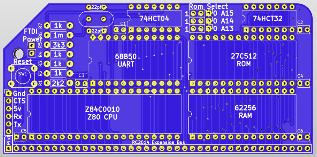

This is essentially a cut down version of the RC2014 Mini, with things like the Pi Zero connector, power socket and LED, and keyboard connector removed. This smaller component count not only reduces the price, but also the size of PCB required, so it matches the RC2014 module appearance.
The RC2014 Micro includes a very short and to the point assembly guide, but a more detailed assembly guide can be found here
Whilst the RC2014 Micro is a full RC2014 computer in it’s own right, there are a few upgrades which you might want to consider before you start to assemble it. For example;
- Add chip sockets. This will reduce the likelihood of damage to the ICs whilst soldering and also allow some limited upgrades at a later date.
- Use 3 pin straight headers and jumpers for the ROM select pads. This will let you access all 8 of the 8k banks on the ROM – not that there is anything else hidden away on the ROM, of course. Or is there…?
- Use a 2 pin header and jumper for the FTDI Power pads. That way, if you are powering your RC2014 Micro from the expansion header, you can still use a FTDI cable for serial communication.
- Add a 40 way right angle pin header on the RC2014 Expansion Bus. This allows you to connect your RC2014 Micro to a Backplane 5, Backplane 8 or Backplane Pro, and expand it’s capabilities with some of the other RC2014 modules. Alternatively, use a 40 pin socket for a single module to be added.
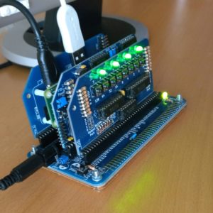
If you chose to add a header and connect your RC2014 Micro a backplane, there are a lot of modules which will expand its capabilities, such as the Digital Input, Digital Output, Joystick, ESP8266 Wifi, YM2149 Sound Card, Prototype board, or many of the 3rd party modules designed for RC2014. Shown below is a RC2014 Micro plugged in to a Backplane 5 with a Pi Zero Serial Terminal and a Digitial I/O Module, allowing it to be used with just a monitor and USB keyboard.
Note that if you are powering your RC2014 Micro from a backplane, you should not power it from a FTDI cable at the same time.
Software
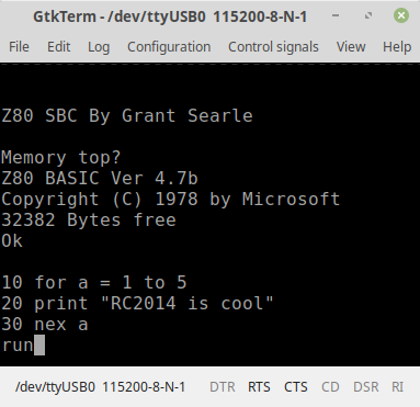
The RC2014 Micro comes with Microsoft BASIC and SCM on ROM. Setting the jumpers on the ROM Module will determine which of these boots when the RC2014 is powered on.
Microsoft BASIC was used by many computers in the late 70s and early 80s, including TRS80, Apple II, Commodore PET, VIC-20, C64, IBM PC Jr etc. The particular variant supplied with the RC2014 Micro is derived from the NASCOM 2, with modifications by Grant Searle. These modifications essentially remove commands that relate to NASCOM 2 specific hardware and also adds commands to deal with Hex or Binary numbers. For more information see the manual for NASCOM 2 BASIC and Grant Searles modifications
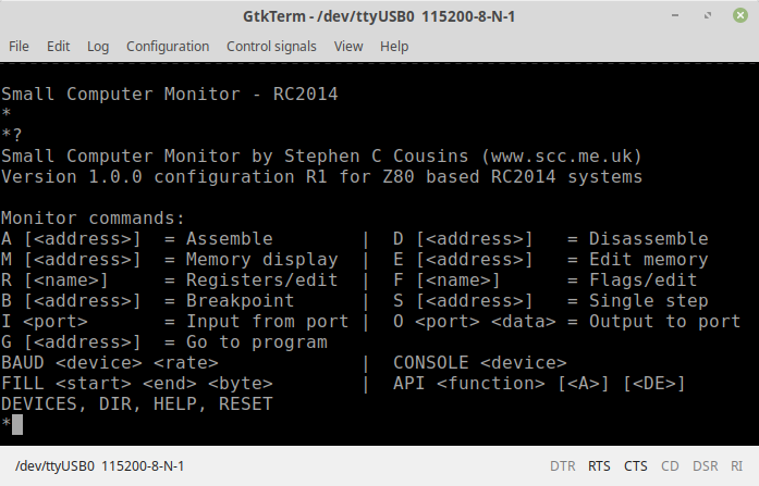
Small Computer Monitor, or SCM, is a Z80 monitor ROM which allows you low level access to the RC2014. This includes assembling and disassembling Z80 assembly code, direct port access, memory manipulation, as well as single stepping through code, examining registers and setting break points. It also features the ability to load Intel .hex files in to memory. Information on SCM can be found here, and the tutorial is highly recommended.
Using The RC2014 Micro
Before powering on your RC2014 for the first time, take a moment to double check all solder joints for solder bridges, dry joints, or missed joints. Ensure all components are orientated the right way and chips are soldered or pressed in to their sockets firmly. Set the jumpers on the ROM Module for either BASIC or SCM. If you are powering the RC2014 from the FTDI cable, ensure that the FTDI Power link is in place.
Connect your FTDI cable to your computers USB port, and fire up your favourite terminal emulator. (If you don’t have a favourite terminal emulator, then TeraTerm for Windows, GtkTerm for Linux, or MiniCom for Mac are recommended). Ensure that your terminal emulator is using the serial port that your FTDI device shows up as, and is set to 115200 baud, 8 bits, No Parity, 1 Stop Bit (8-N-1 is the default on most devices). Connect the FTDI header to the RC2014, in accordance with the colour pinout as described above, and hit the reset button. You should then be greeted with the welcome message for either BASIC or SCM.
If booting to BASIC for the first time, it will ask for Memory Top? Just hit return here for the full 32k to be available. Subsequent resets will ask for Cold or Warm start. Cold clears the memory before starting, Warm retains whatever was in memory before the reset. You’re then ready to start programming in BASIC!
If booting to SCM you will be greeted with a welcome message and a * prompt. Hit ? [return] for a summary of commands. You’re then ready to start programming in Z80 assembly language!
Troubleshooting
If your RC2014 Micro fails to boot up, don’t worry. Most faults can be traced visually, and few faults lead to permanent damage. All the chips should be cool to the touch, though, so if it is not booting and one of them is getting hot, remove the power quickly!
Read through the Troubleshooting Guide here for pointers on what to look out for. If you are still having issues, use the Contact me link, or visit the RC2014-Z80 Google Group. Be prepared to explain exactly what the issue is, and what steps you have already taken. It may help to provide clear photos of the assembled boards too.
Bill of materials
- 1 RC2014 Micro PCB
- 1 Z80 CPU
- 1 27C512 EPROM
- 1 62256 RAM
- 1 MC68B50
- 1 74HCT04
- 1 74HCT32
- 4 1k resistor
- 1 1M resitor
- 1 2k2 resistor
- 1 3k3 resistor
- 1 7.3728 Mhz Xtal
- 2 22pf ceramic cap
- 6 100nf
- 1 Tactile Switch
- 1 3 pin ra header
- 1 6 pin ra header
- 1 jumper