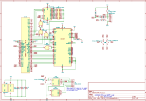
This flexible module is designed as an economic serial module for RomWBW machines. Either as the primary UART0 port or in addition other modules. At its heart is a 16C550 is a single UART chip running at 115,200 baud.

RomWBW supports up to 8 UART ports from UART0 to UART7, and this module is designed appear as the default UART0, or any port up to UART7. The RCZ80_std.rom build of RomWBW 3.4.0 supports 2 ports on 0xA0 and 0xA8, and from 3.5.0 onwards 4 port are supported on F0, F8, A0, A8. A custom build of the ROM will also support up to 8 ports with 0xC0, 0xC8, 0xE0 and 0xE8 enabled.

Click image to open pdf schematic
Assembly
Assembly takes the same approach as other RC2014 Modules. Start with the lowest components and build up to the highest. Note that the ICs need their orientation to match the the silkscreen. Pay particular attention to the PLCC44 socket which must be orientated with the angled corner and hole mark to the bottom right where there is a circle on the PCB. The 16C550 chip will only fit in the socket one way. When fitting the two rows of header pins for the port selection, adding a couple of jumpers when soldering will ensure they are parallel and at the correct spacing.
Unless you have specific requirements, the spare pads under the ‘393 chip and the pads marked Clk1/Clk2 and the Tx1/Tx2/Rx1/Rx2 pads can all be ignored. If a single row header is used then Port A will appear on the RC2014 Standard Bus on pins 35 & 36. If a double row header is used, prepare it as shown in this guide. Port A can then be set to appear on the Enhanced Bus on pins 59 & 60 – see Useful Hacks later on this page.
Hardware
The 16C550 chip basically sits between the Z80 bus and the FTDI compatible header. From the Z80 perspective, all the data lines, /RD, /WR and A0, A1 & A2 connect directly. /Reset goes through both inputs of a NAND gate which acts as a NOT gate to give the 16C550 the active high signal it needs. The interrupt goes through both inputs of a NAND gate to the /INT pin on the Z80 to indicate that data is waiting.
The Chip Select on the 16C550 is driven from a 74HCT138. The ‘138 is active when A4 and /IORQ are low and both M1 and A7 are high. A3, A5 and A6 will then select which base port (80, 88, A0, A8, C0, C8, E0 or E8) the CS signal is on. Through a row of jumpers this signal is routed to /CS on the 16C550
When /CS is active, A0, A1 and A2 determine which port is being written to or read from. This means that 8 individual ports will address the 16C550. Eg if the base port is 0x80, then 0x81, 0x82, 0x83, 0x84, 0x85, 0x86 and 0x87 are used. See the 16C550 datasheet for the specific details of how each of these addresses are used.
The 7.3728 MHz clock that drives the CPU goes via a 74HCT393 counter to divide it by 4 to 1.8432 MHz, which results in a baudrate of 115,200 buad. For alternative clock speeds or baud rates, see below.
On the output side, only the Tx, Rx, CTS and RTS are required, and these come out to 6 a pin header via current limiting resistors. The Tx and Rx also go through some pre-joined jumper pads to bring Port A to Tx1/Rx1 on the backplane. If you are using another UART that is connected to the backplane, or you want to redirect Port A to Tx2/Rx2 on the Enhanced Bus then see below.
Useful hacks
This module is designed with the most common use cases in mind. This is that a 7.3728 MHz clock is used, the RC2014 is connected to115200 baud devices and that Port A is on the Standard Bus. There are reasons why this might not always suit every RC2014 so some optional PCB hacks are made easy on the board.
Alternative clock / baudrates
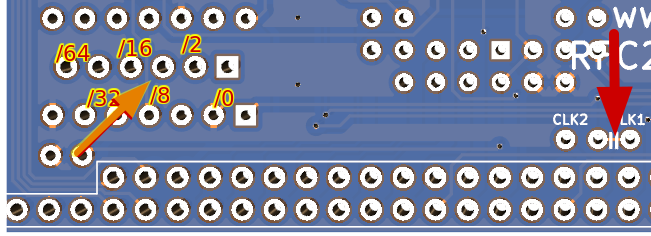
By default this module takes the 7.3728 MHz clock from Clock 1 and divides it down to 1.8432 MHz which results in 115200 baud. If you wish to use the clock from Clock 2 there is a jumper that needs to be cut, then a link soldered from the center pin to Clk2. The copper is exposed on the back of the PCB as marked by the red arrow. You need to cut this with a sharp knife before soldering a link (or adding pins and a jumper) to Clk2

The clock signal is routed to the 74HCT393 counter which divides it down by 4. A slower clock will result in a slower baudrate. Dividing 7.3 MHz by 8, for example will give 57600 baud. The additional dividers are on the 6 pads under the ‘393. You will need to cut the track on the back of the PCB as marked with the orange arrow and solder a wire from one of the 6 divisions to pin 18 on the 16C550.
Tx Rx Backplane Routing
Port A of the 16C550 is connected to the left hand 6 pin connector and pins 35 & 36 of the Standard Bus. If you wish to disconnect this port from the bus, maybe because you have another UART connected to the bus, you will need to cut both tracks as marked. You can also add header pins and jumpers if you want to reconnect the ports to the bus or swap from Tx1/Rx1 to Tx2/Rx2.

Software
RomWBW has software support for the 16C550 UART enabled by default. On startup RomWBW will probe the ports it expects to find a 16C550 on, and will load the drivers if one is found.
RomWBW v3.4.0
The default config expects to find a SIO/2 or a 68B50 on port 0x80 and 0x82, and a 16C550 on port 0xA0 and 0xA8. If you are using this version of RomWBW, simply set the jumpers on this module to port A0 and A8 and it will work. Depending on what other UARTs are found, Port A may be the default console port, although double tapping the Space Bar will set this as the active port. The config file can, or course, be edited so that any other port can be used. See below.
RomWBW v3.5.0 onwards
The default config expects to find a SIO/2 or a 68B50 on port 0x80 and 0x82, and a 16C550 on port 0x80, 0x88, 0xA0 and 0xA8. If you are using this version of RomWBW, simply set the jumpers on this module to any two of 80, 88, A0 or A8 and it will work. Depending on what other UARTs are found, Port A may be the default console port, although double tapping the Space Bar will set this as the active port. The config file can, or course, be edited so that any other port can be used. See below.
Microsoft BASIC, SCM or CP/M on Mini II, Classic II or RC2014 Pro
Currently the version of BASIC, SCM and CP/M supplied with the Micro, Mini, Mini II, Classic, Classic II or RC2014 Pro does not support 16C550 UARTs.
Custom RomWBW builds
If you wish to use more than 4 UARTs which the default RomWBW enables, or need to use different ports then creating a custom RomWBW build is straightforward. See the ReadMe.txt in the /Source directory for full detailed instructions. For the broad overview, however, you need to download RomWBW from GitHub, open RCZ80_std.ASM in the /Source/HBIOS/Config directory and add the following lines
UARTENABLE	.SET	TRUE		; UART: ENABLE 8250/16550-LIKE SERIAL DRIVER (UART.ASM)
UARTCNT		.SET	4		; UART: NUMBER OF CHIPS TO DETECT (1-8)
UARTOSC		.SET	1843200		; UART: OSC FREQUENCY IN MHZ
UARTINTS	.SET	FALSE		; UART: INCLUDE INTERRUPT SUPPORT UNDER IM1/2/3
UART4UART	.SET	FALSE		; UART: SUPPORT 4UART ECB BOARD
UART4UARTBASE	.SET	$C0		; UART: BASE IO ADDRESS OF 4UART ECB BOARD
UART0BASE	.SET	$80		; UART 0: REGISTERS BASE ADR
UART0CFG	.SET	DEFSERCFG	; UART 0: SERIAL LINE CONFIG
UART1BASE	.SET	$88		; UART 1: REGISTERS BASE ADR
UART1CFG	.SET	DEFSERCFG	; UART 1: SERIAL LINE CONFIG
UART2BASE	.SET	$A0		; UART 2: REGISTERS BASE ADR
UART2CFG	.SET	DEFSERCFG	; UART 2: SERIAL LINE CONFIG
UART3BASE	.SET	$A8		; UART 3: REGISTERS BASE ADR
UART3CFG	.SET	DEFSERCFG	; UART 3: SERIAL LINE CONFIG
UART4BASE	.SET	$FF		; UART 4: REGISTERS BASE ADR
UART4CFG	.SET	DEFSERCFG	; UART 4: SERIAL LINE CONFIG
UART5BASE	.SET	$FF		; UART 5: REGISTERS BASE ADR
UART5CFG	.SET	DEFSERCFG	; UART 5: SERIAL LINE CONFIG
UART6BASE	.SET	$FF		; UART 6: REGISTERS BASE ADR
UART6CFG	.SET	DEFSERCFG	; UART 6: SERIAL LINE CONFIG
UART7BASE	.SET	$FF		; UART 7: REGISTERS BASE ADR
UART7CFG	.SET	DEFSERCFG	; UART 7: SERIAL LINE CONFIG
Change the UARTCNT .SET 4 to the amount of UARTs you wish to use. If using more than 4 then update the UART4BASE, UART5BASE, UART6BASE and UART7BASE addresses as appropriate. Then run Build from the RomWBW root directory to create your new RCZ80_std.rom file and burn this to your ROM. If you don’t have an EPROM writer, then this RomWriter for 39SF040 is perfect.

Bill Of Materials
1 RC2014 16C550 UART PCB
1 16C550
1 74HCT00
1 74HCT138
1 74HCT393
1 40 pin header
1 PLCC44 Socket
2 14 pin narrow DIL socket
1 16 pin narrow DIL socket
2 8 pin header
1 2 pin header
1 6 pin RA header
2 jumper
3 1k resistor
2 100k resistor
3 100nf
