I knew there would be some stumbling blocks with this Retro Challenge, but, hey, it wouldn’t be a challenge if everything was just nice and simple. However, I seem to be beset by little stupid technical issues that aren’t necessarily retro in nature.
However, the fact that you’re reading this does at least mean that my blog is working again! I ran some updates last week, and it caused some issues with a plugin meaning I had no way of adding, editing or modifying any posts. I’ve now got that tracked down to the Poll plugin and disabled it. So, yay, I’m back!
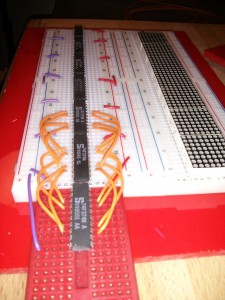
So, part of this challenge is to use LEDs, and the little 8×8 matrix modules I found seem ideal. I had initially intended to design a PCB to mount a bunch of these on, but due to time constraints, it was looking very unlikely I’d get them designed, ordered, manufactured and delivered by the end of the month, let alone time for testing. So I decided to go Old Skool, and do this part on a breadboard. Well, 2 breadboards, as they each need a driver chip. Although, it’s actually 3 breadboards, as 2 aren’t quite big enough. Not to mention the other breadboard with the supporting circuitry on. I made a start on this last night;
After an hour or so, the enormity of this began to dawn on me. There’s 7 matrix modules. Each with 8 pins on X and 8 pins on Y axis. All the X pins need to connect between them, and then to a 20 pin latch chip. All the Y axis pins go to a latch chip themselves. All the latches have a 8 bit data bus that connected them all together. Plus the controller. And power rails. That’s over 450 wires I’ve got to trim and push in!
At which point I decided to abandon that idea, and go back to a PCB plan. It would mean using a UK company in order to get it manufactured in time, and that would cost a small fortune for a one-off. But I gave it a go. 4 hours later I realised that trying to minimise the amount of space the board took up by mounting the display and driver chips on opposite sides made the routing impossible. I tried a couple more ideas, and then gave up on the PCB plan. I have, however, ordered a load more jumper wires from eBay this morning!
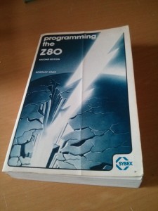
Talking of eBay, this arrived in the post yesterday;
When I first started to investigate Z80 CPUs a few months ago, this book was widely held as the difinitive guide. It is out of print, but there are scanned PDF versions out there if you know where to look. For better or worse, they are not OCRd PDFs, and despite nearly finishing reading this, I’ve never really got on so well with books on a tablet, so I managed to pick this up cheap from eBay. For a reference book to skip backwards and forwards, or flick through looking for something I think it’s better than the electronic equivalent.
How is the Z80 assembler side of the project going I hear you ask? Well, yeah, it’s coming along. Slowly. With such a limited amount of commands even the simplest of things really has to be broken down to a very basic level. What do you mean I can’t just multiply by 7? Well, I had some little test-lets that I was going to try out last night before I ended up breadboarding, however, due to some other glitch, the Z80 Emulator website does not run on my Linux machine at home. This could be quite inconvenient. But I’m sure I’ll find a way around it sooner or later. Isn’t that part of what a challenge is?

