The ESP8266 Wifi Module can easily be reprogrammed with either the Arduino IDE, ESP Flash Download Tools or ESPTool.
If using the Arduino IDE, you will need to add support for ESP8266 devices. To do this, go to File > Preferences > Additional Boards Manager URLs: http://arduino.esp8266.com/stable/package_esp8266com_index.json You can then select Generic ESP8266 from the Board menu
The default settings should work fine, although for optimum use, you may want to set the following parameters;
- CPU Frequency – 160MHz
- Flash size – 4MB (FS: 3MB, OTA: 512KB)
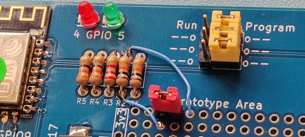
Note that GPIO4 and GPIO5 are connected to the LEDs, so if you are using firmware which expects to use the pins (such as Zimodem) you will need to modify the sketch to use point at two unused ports (such as GPIO9 and 10)
A full tutorial on using the Arduino IDE, or other tools is beyond the scope of this website, but there are a lot of guides out there for different skill levels.
To put the ESP8266 Wifi Module in to programming mode, remove it from your RC2014 . The 3 jumpers at the top of the board need to be moved from Run to Program. This redirects the Tx and Rx to the FTDI header, and pulls GPIO0 low to put it in to programming mode. Connect a 5v FTDI cable to the 6 pin header on the right. Push the reset button before uploading your new firmware.
Important note for 3v3 FTDI Logic Levels
Some FTDI type devices use 3v3 logic levels for the Tx and Rx signals, even if they have a 5v Vcc line. This is fine with a RC2014, as a 3v3 signal is high enough to trigger a logic level 1, and the FTDI devices are 5v tolerant.
However, the ESP8266 is not officially 5v tolerant. Therefore the Tx signal from the RC2014 goes via a resistor divider to drop it down to 3v3 before it gets to the ESP8266
If you use a FTDI type device with 3v3 logic levels, this also goes through the resistor divider, which means only about 2.1v is detected on the ESP8266, which is not enough to register as a logic 1.
To overcome this, R2 needs to be bypassed when programming. Depending on your dexterity, and how often you expect to reprogram it, there are a few suggestions. Holding a jumper cable across R2 is the simplest, although physically tricky. Soldering a wire across the underside of R2 works great, although you will need to unsolder it before plugging the module back in to your RC2014. Using the prototype area to add a couple of header pins connected to either side of R2 is a good option if you will be testing out various iteration of software