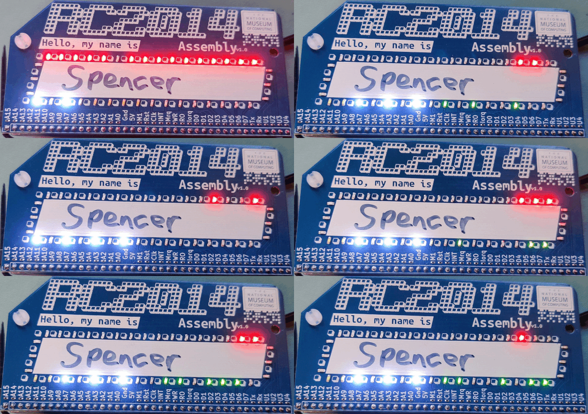
Every conference, meetup or gathering where people might not know each other needs a name badge. In ancient times this used to be a sticky label with “Hello, my name is” and a space for attendees to write their name. Tech conferences have bought the name badge right up to date with screens, buttons, microcontrollers, wifi, and anything else somebody might need to tell people who they are. Just take a look at Badgelife on Hackaday to see what goes on.

For the RC2014 Assembly I wanted something more conventional, but with a bit of a twist. Initially this was just going to be a RC2014 Module shaped PCB with silkscreen on it for people to write their name on. But, well, feature creep got the better of me. Why not add some LEDs!

Click image to open PDF schematic
Hardware
The badge comprises of 38 LEDs with a resistor each. These are connected to each of the address lines (red LEDs), data lines (green LEDs), control signals (white LEDs), and serial/user (orange LEDs). Most LEDs go down to ground, although active low signals go to 5v

This turns the humble name badge in to a giant logic analyser to see what is going on inside the RC2014 bus. Theoretically you can use this to debug what your RC2014 is doing, although realistically, at 7.3728MHz it means that all the LEDs are on, but at a varying brightness. You have to slow the clock right down to see anything of any value.
Also note that the RX signal is pulled up to 5v by the badge, so your RC2014 will not receive any serial input if the badge is plugged in. To get around this, you will need to remove the RX pin from the header before installing it, or remove the tiny resistor next to the RX pin. But, hey, any v1.0 PCB will need some kind of bodge, right?

My Badge
Knowing how the badge can be used, I decided to build myself a special RC2014 to take advantage of the LEDs prior to the RC2014 Assembly.

This comprises of an RC2014 Micro that uses the Slow Clock circuit as found on the Dual Clock Module. This runs at just a few Hertz, so there is a distinct On/Off of each of the LEDs.

I wrote some very simple Z80 code that reads the value from every single address and writes it to the output port of that value. This ensures that every address, data, and control LED except for the Reset gets used. With this burned to ROM the RC2014 and the badge can be connected by a straight pin header and socket. A small cheap USB battery bank was then hung from the badge via a cable tie sling. It was connected to the reverse mounted FTDI header using a custom cable made from a USB-A to USB-A cable, a 6 pin socket and some Sugru. The cheap battery bank didn’t have any current sensing, so was able to run the badge continuously for about 3 hours before being swapped out for another one.


This went down very well at the RC2014 Assembly. Despite conference badges being driven by micro controllers, RISC-V processors, or FPGAs, I think this might be the first one running on a genuine Z80. That surely qualifies for an entry in to the Badgelife Hall Of Fame, right?
