
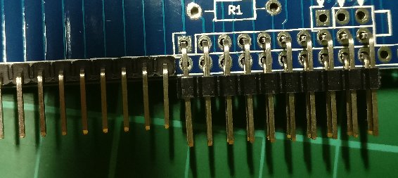
If you are planning on installing a module that makes use of the additional signals available on the Enhanced Bus with a Backplane Pro, then you will need to use a double row right angle header on the module.
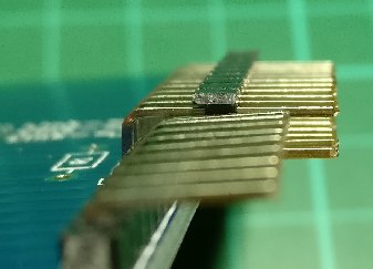
Unfortunately, the profile of single and double row headers are quite different, and they cannot be mixed and matched on the same module.

Removing the excess pins from a double row header is quite quick and simple, although if you mess up you could end up with pins out of alignment, and nobody wants that! However, there is a neat little trick that makes things even easier.
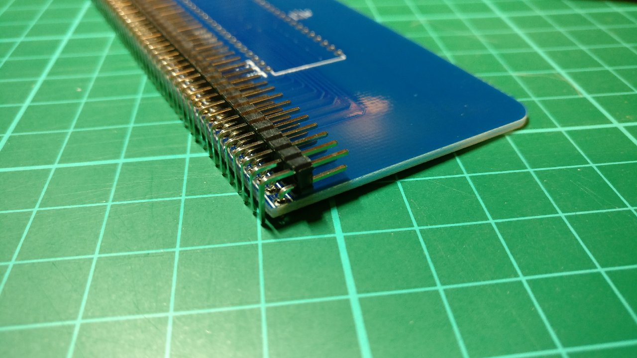
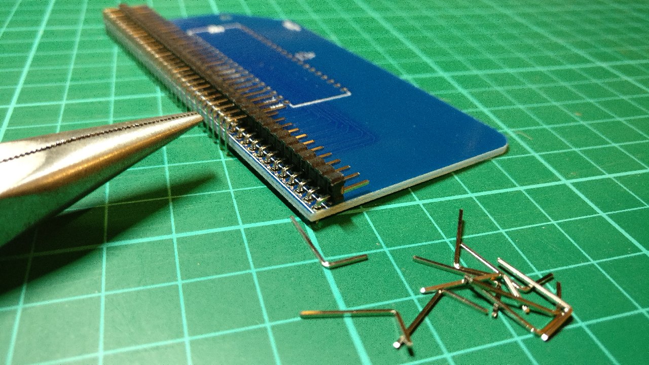
Start by putting the double row header on the module PCB backwards, so that the short pins all go through the holes. (Don’t solder them!). Instead of using your module PCB then anything such as Veroboard could be used, just ensure that only one row (the short pins) go thought. This will ensure that they stay in perfect alignment.
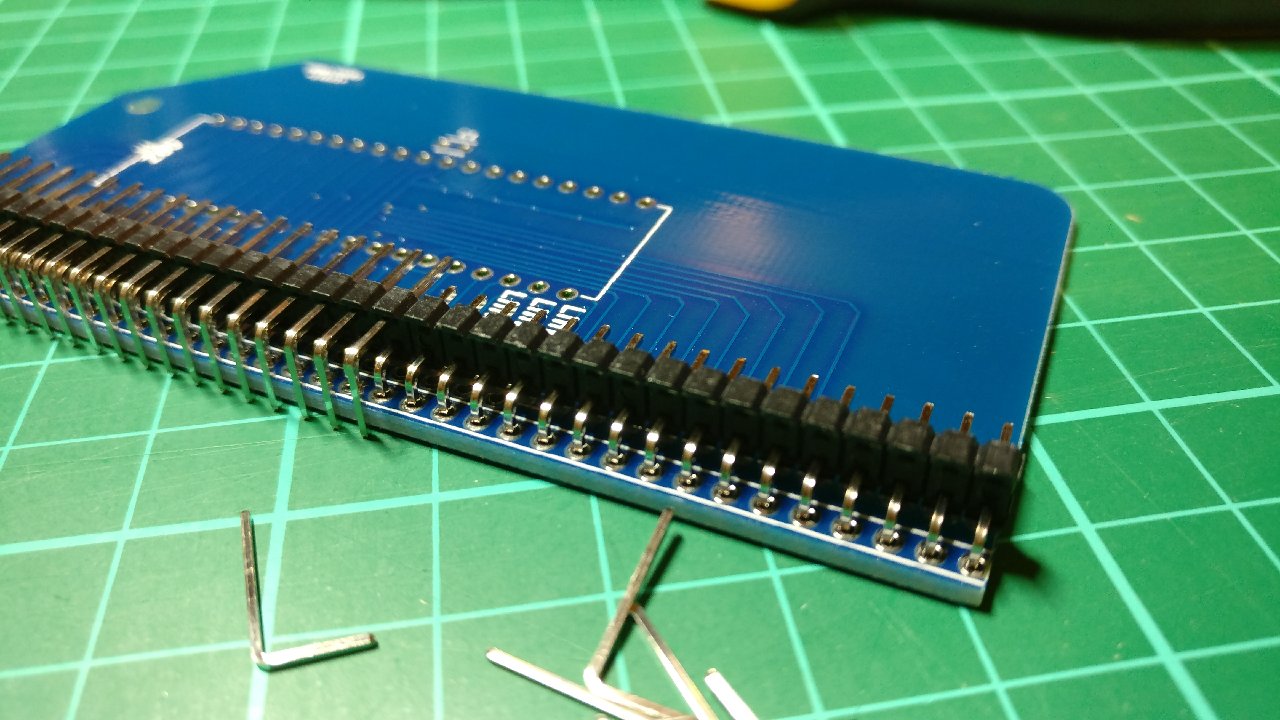
Then, with a pair of needlenose pliers, start to remove the long pins, beginning on the right hand edge
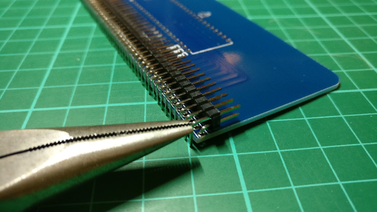
They should come out quite smoothly, although you might need to give some a little twist to loosen them up.
Keep on going until there are 16 pins removed.
Most modules have 10 Enhnaced Bus pins, so skip over 10 pins before removing the rest. (Note that because the pins are upside down, you can’t use the marking on the module as a guide as this is of-centre)
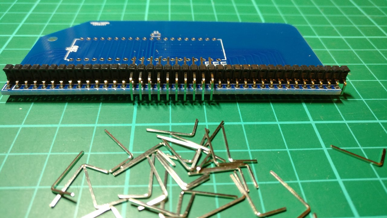
Of course, if your module has more than 10 Enhanced Bus pins, skip over this amount instead.
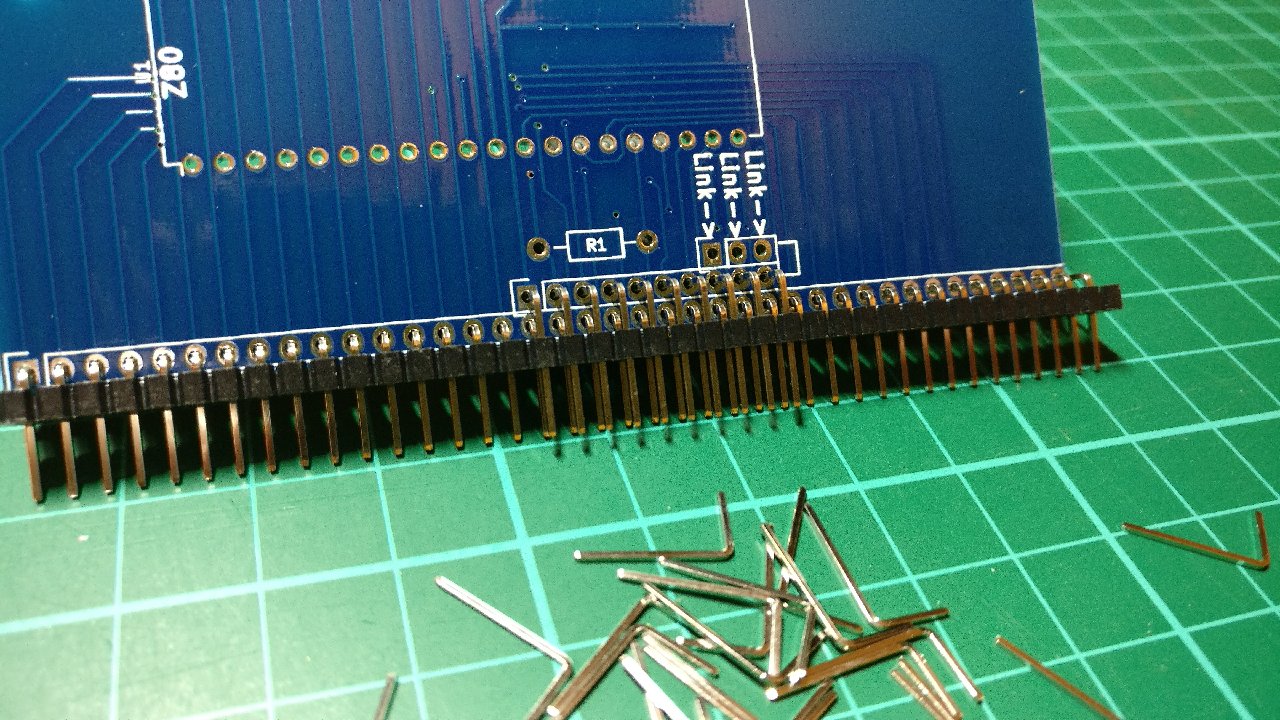
Remove the pins and put the header in the right way up. It should all line up, and you will have one pin (pin 40) to remove at the very end.

You can now solder the header to the module.