Simple Guide To Getting CP/M Running On RC2014

With the right software, hardware and settings, getting CP/M running on a RC2014 is very easy.  This post is a guide to doing just that.  It assumes you are already familiar with the RC2014 and have built and tested your RC2014 running BASIC.

Required hardware

Optional Hardware

Software

Both the Pageable ROM Module and the Compact Flash Module are available with the CP/M Monitor pre-programmed on to ROM at 0x8000.

The Compact Flash Module is also available with a pre-programmed 128mb compact flash card which contains CP/M as well as the essential software required to get you up and running

Settings

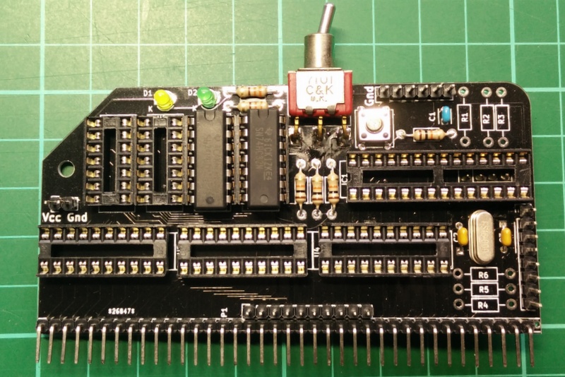
The 64k RAM Module needs to be set to full 64k (ie start address at 0x0000) and in pageable mode.  For this, all 4 jumpers need to be set to the right hand settings as shown below.  If you soldered a link where indicated by the silkscreen, this needs to be remove as this is the page pin

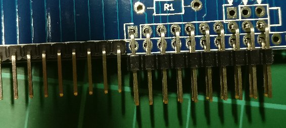
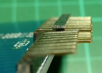
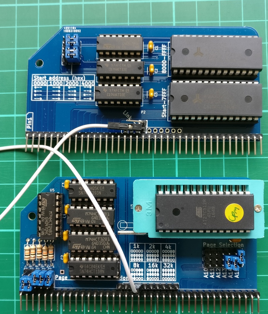
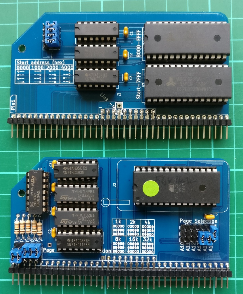
The Pageable ROM Module needs to be set for an 8k page and starting at 0x8000.  See photos below for details.

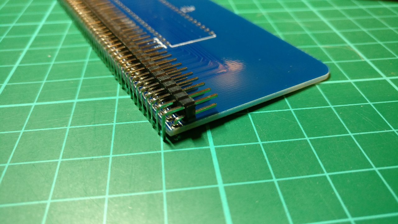
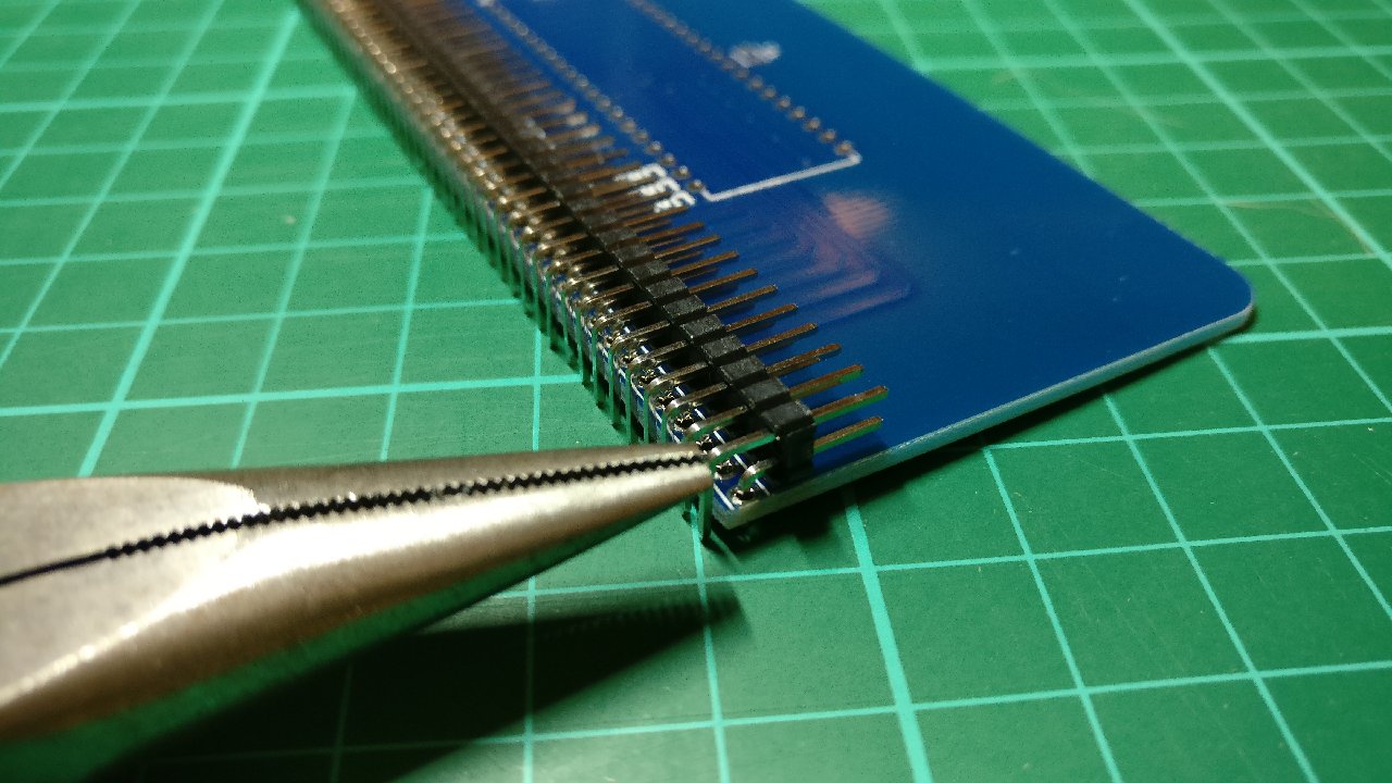
The Page Pin from the ROM needs to be connected to the Page Pin on the RAM.  If you have the Backplane Pro and have installed the double header pins supplied with that then nothing further needs to be done.  If you are using a Backplane 8, however, you will need to add a jumper cable between the 4th pins on the 10 pin Enhanced Bus header.  See the photos below to illustrate either scenario

Then it is simply a case of installing all the modules (if using Backplane 8 ensure you have links between slot 2&3 or 6&7 so you can use the outer slots), connecting FTDI cable or monitor & keyboard if you are using the Pi Zero Terminal, inserting the compact flash card and applying power.

[On power up, a small bootloader will copy itself and a modified CP/M console from 0x0000 (ROM) up to 0xA000 (RAM), then page out the ROM and page in the lower 32k RAM, then copy Grant Searles CP/M Monitor (as modified by Mitch Lalovie and tweaked by me) back to 0x0000 (RAM) and run the monitor from there]

You will be greeted by a “Press [space] to activate console” message, and after pressing space you will be in to the monitor.

(Note that the B option for BASIC will not work with this hardware set up. If you want to use BASIC, either set the A15 Page Selection jumper to 0, or download a copy of mbasic to CP/M)

Press X followed by Y and it will boot CP/M from the compact flash card and you will be at the A> prompt.

The compact flash card is pre-formatted with 16 drives from A: to P:  The A: drive has DOWNLOAD.COM which is needed to transfer files on to the CF card.  Drive C: has CP/M utilities such as TYPE.COM ED.COM, STAT.COM etc.

To copy files and programs on to the CF card you will need to connect to your RC2014 over a FTDI cable, and either use Grant Searles Windows File Packager or manually package the files with a text editor.  When copied over the FTDI connection it will initiate A:DOWNLOAD.COM which will then take the file and put it on to the current selected drive.  Note that the flow control on the 68B50 is minimal with this setup, so a 1ms delay between characters is suggested to give consistently successful results.

After that, I highly recommend using a torch otherwise you will almost certainly end up being eaten by a Grue

If you are planning on installing a module that makes use of the additional signals available on the Enhanced Bus with a Backplane Pro, then you will need to use a double row right angle header on the module.

Unfortunately, the profile of single and double row headers are quite different, and they cannot be mixed and matched on the same module.


Removing the excess pins from a double row header is quite quick and simple, although if you mess up you could end up with pins out of alignment, and nobody wants that!  However, there is a neat little trick that makes things even easier.

Start by putting the double row header on the module PCB backwards, so that the short pins all go through the holes.  (Don’t solder them!).  Instead of using your module PCB then anything such as Veroboard could be used, just ensure that only one row (the short pins) go thought.  This will ensure that they stay in perfect alignment.

Then, with a pair of needlenose pliers, start to remove the long pins, beginning on the right hand edge

They should come out quite smoothly, although you might need to give some a little twist to loosen them up.

Keep on going until there are 16 pins removed.

Most modules have 10 Enhnaced Bus pins, so skip over 10 pins before removing the rest. (Note that because the pins are upside down, you can’t use the marking on the module as a guide as this is of-centre)

Of course, if your module has more than 10 Enhanced Bus pins, skip over this amount instead.

Remove the pins and put the header in the right way up.  It should all line up, and you will have one pin (pin 40) to remove at the very end.

You can now solder the header to the module.

Iterations of a SD Module

From the very earliest days of the RC2014, back when the whole thing was a bunch of wires and chips on a breadboard and before the RC2014 even had a name I knew that it needed some kind of storage.  The obvious solution to me was via SD card.  I had already made a simple PS2 keyboard and 4 line LCD display interface from an Atmel ATMEGA328, and it was easy enough to add an SD card interface.  The ‘328 was connected to the yet to be named RC2014 via serial, so anything I could type on the keyboard could be passed through to the RC2014.  Likewise, the contents of a text file on the SD card could also be put on the serial port.  Intercepting keystrokes like F1 would send the text file 1.bas to the RC2014.

It kind of worked, but was clunky at best.  The text files had to be created on a PC as there was no way to save anything – although I thought about monitoring the keyboard for SAVE to be typed which would be replaced by LIST and the stream coming back would be saved to SD.  But that was even more clunky and hacky.

Once the RC2014 appeared in PCB form, I returned to the idea of an SD card storage device.  This time it was to load raw machine code from SD to RAM – again, via an ATMEGA328 but this time connected via a Z80 port (Essentially, the same circuit as the Digital I/O Module)

The idea here would be a simple bootloader ROM would run on the RC2014.  This would set one of the bits of port 0 high so the ‘328 would know to load the first byte from a file on the SD card on to the data bus.  Once the Z80 had loaded this in to RAM it would toggle the bit and the next byte would be read until the whole file was loaded.

Although this worked, it wasn’t a solution I was particularly happy with.  The main reason was that it had very limited functionality and relied on a custom ROM image.

What I wanted was a way to fill the RAM without worrying about what’s in the ROM (or even having a ROM), and bypassing the Z80.  An old idea that I had for making an EPROM burner was recycled in the form of this prototype;

This used a couple of 74LS393 counters connected to the address bus via 74LS245 to count from 0 to 65535 (ie the whole Z80 memory address space).  A bus request (BUSRQ) from the ‘328 asked the Z80 to disconnect itself from the bus.  When this is acknowledged (BUSACK) the ‘245s have control of the bus and can increment the address from a pulse from the ‘328.  The prototype proved the concept worked, so time to spin up a simple board to take things further.

The first spin of the board was focused on the Z80 interface with the SD pins and any spare GPIO pins from the ‘328 bought out to headers.  I still hadn’t decided yet how the SD card would actually be fitted.  Every SD card socket I could find was surface mount, and if this was to be made in to a kit, I wanted to avoid surface mount components if possible.

The next spin of the board refined more of the control circuitry.  The spare GPIO pins had been connected to switches, LEDs and some of the bus lines.  Not everything quite worked as planned, as the subtle bodge wires allude to.  In hindsight, using black solder resist for a prototype board wasn’t such a great idea either.  However, I got it to work and was able to get the firmware on the ‘328 doing what I wanted it to do.

I had been using a cheap Chinese SD module to connect the ‘328 to an SD card, and these actually work very well as well as being a kind of standard, so to get around the surface mount issue, I decided to use the whole module in the finished product.  Oh, and as you can see, there really isn’t much spare PCB space for an SD card socket either!

With a bit of swapping around, I managed to free up an analog GPIO pin that I could connect to a potentiometer.  This works as a crude file selector.  The initial firmware I wrote for the ‘328 works, and loads an image from SD card in to RAM, or dumps the whole contents of memory in to a file on the SD card.  Scott Lawrence has updated this to give access to different file images and protects these against accidental overwriting.

So far, this is the best SD card storage for the RC2014 that I’ve made.  I wanted to share this though to give you an idea of how a new module is created, from conception, through prototypes and to final product.