HDMI and USB Keyboard Support

So, the RC2014 is a great little computer.  We all know that.  However, to communicate with it, it is easiest to use the serial port and hook it up to a laptop or desktop PC.  This makes detracts from the fact that it is small, portable and cheap as well as missing the point of running code on such a basic computer.  So I’ve been looking for a solution to this.

Back when this was still running on a breadboard, I hooked up an Atmel ‘328 that was connected to a keyboard and 4 x 20 LCD display.  It communicated with the RC2014 over the serial port and kind of worked ok, although 4 lines was very restrictive and the Atmel couldn’t really keep the screen running and listening at the same time.   I have thought about using a ‘328 to drive a composite output, or maybe some kind of bigger LCD panel, but nothing really struck me as just right.

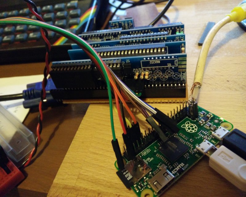
That is, until the kind people at Raspberry Pi released a cheap multifunction interface device a couple of weeks ago!

2015-12-18 22.13.44

(more…)

Retro Challenge – Day 2 – First PCB Designed

So, this is Day 2 of the Retro Challenge.  In case you’re wondering what happened to Day 1, well, Day 1 happened to fall on Pub Night, therefore I was better off giving everyone else one day head start than having a go and probably putting myself back at least a week!

If you’ve read my posts on Retro Challenge so far, you’ll know my first priority is to get about half a dozen or so Printed Circuit Boards designed and sent off to the fabricators.  The tool I am using to do this is KiCad, and the basic workflow is lay out the electrical circuit schematic, create a list of component, match the components up to footprints, lay the footprints out on a board, join up the various pads then create gerber (manufacturing) files.

I have decided to build my Z80 computer in a modular format, with lots of fairly basic PCBs to make up the whole thing.  This should give me flexibility in how I use it and what I do with it going forward.  It also makes the boards easy to design and lay out, and, if necessary, easy to troubleshoot too.  So, with that in mind, I set out this evening with the goal of making the electrical schematic for at least 5 boards.  Starting with the CPU board, which comprises of 1 chip, 1 connector and 1 resistor.  Simples!

KiCad uses libraries of components, so when you lay out a circuit you can pick a resistor, a capacitor, voltage regulator etc.  It’s got loads of chips in the default library that comes with it, but, as I discovered this evening, no Z80! I tried finding a library on line that had one, but couldn’t get anything that worked.  So I had to design my own component – a 40 pin IC! Then, the connector I was going to use was for my Z80 bus, and that had my own designed layout, so that’s another 40 pin component I had to design!  Luckily, a regular resistor was already available!  So, join the appropriate pins up, and voila! A schematic!

Screenshot from 2014-07-02 22:35:38 (more…)