2024 marks the 10 year anniversary since I entered the Retro Challenge in… hmmm… let me see now… that’ll be… 2014! Yes, I remember it well, because Retro Challenge 2014 had a catchy hashtag on Twitter, something like #RC2014.
Well, the good folks behind Retro Challenge approached me and asked if I would consider donating a prize for this years event. There were no prizes back in my day, it was all about likes and subs, and inadvertently starting a new career back then. But, hey, I understand that people like prizes, so I said yes. I said I would like to offer an RC2014 Classic II kit to the winner of the RC2014 category
After thinking about it for a little while, I figured I could come up with something a little bit more special. But before I reveal what that is, and before you skip to the bottom of this post for a sneak peek, I wonder if I should explain what Retro Challenge is. Well, it is a challenge revolving retro computers. The challenge is self-set, and you can do pretty much whatever interests you if it involves a retro computer, and you blog about it to share your knowledge and inspire others. Maybe you want to right software for your old Dragon 32, or get that VIC20 cleaned up, recapped and retrobrited, or scan in the original PDP manuals and upload them to the Internet Archive.
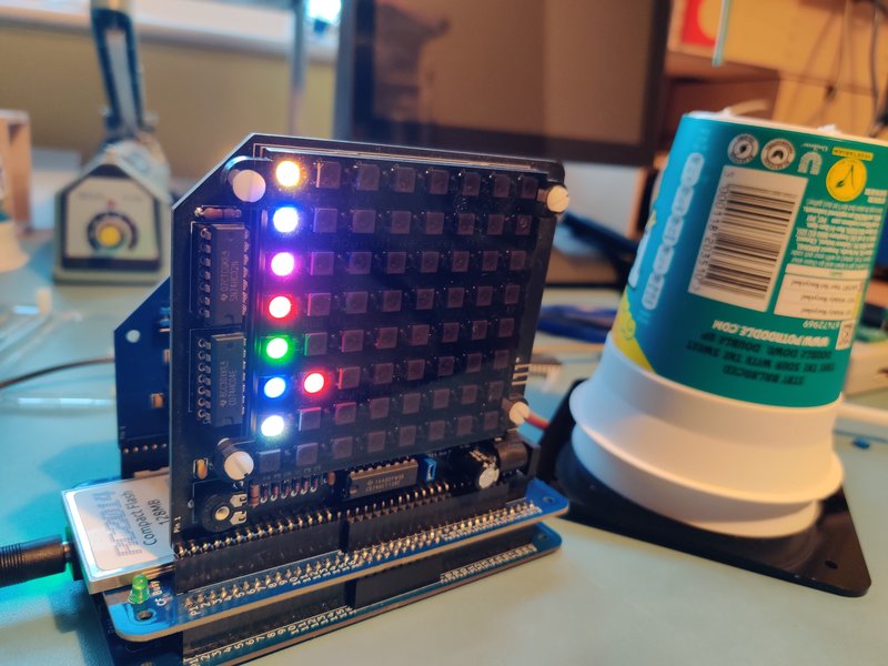
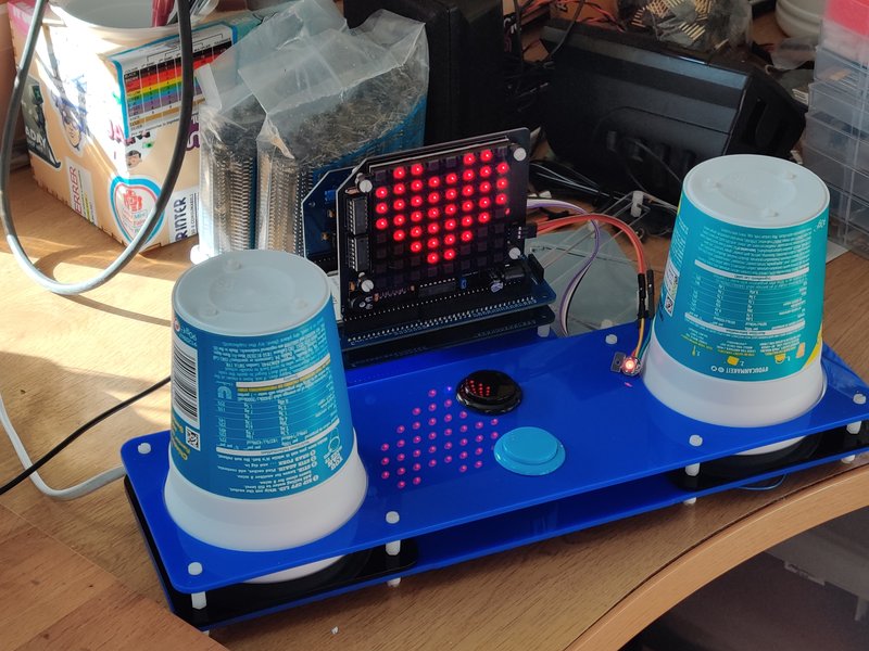
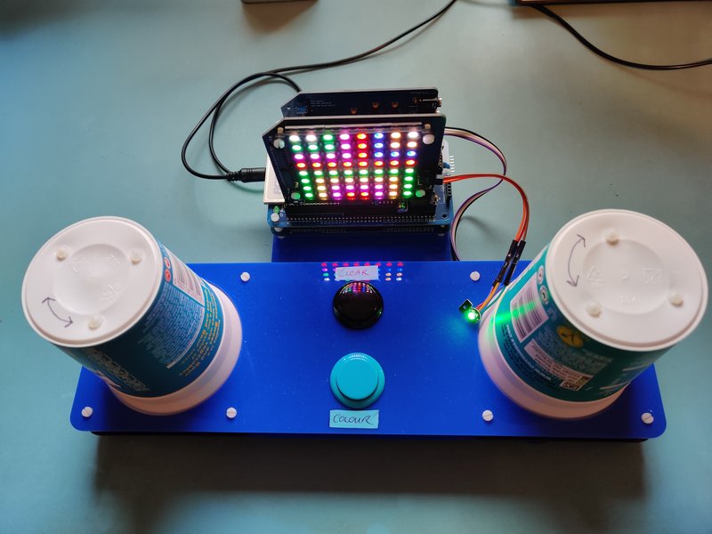
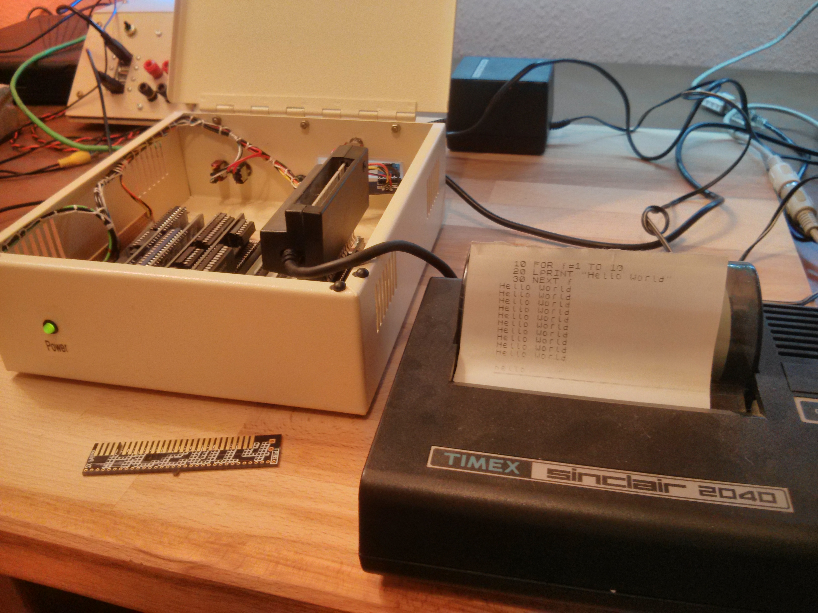
Back in 2013 I had built a Z80 computer on a breadboard that ran BASIC. The challenge I set myself for Retro Challenge 2014 was to make my name appear in lights. More specifically I was going to write Z80 code to do it, using a Z80 computer which I also had to design. You can read more about it here https://rc2014.co.uk/653/retro-challenge-2014/
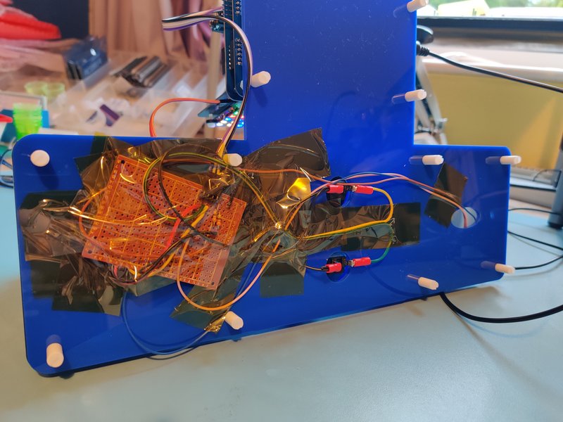
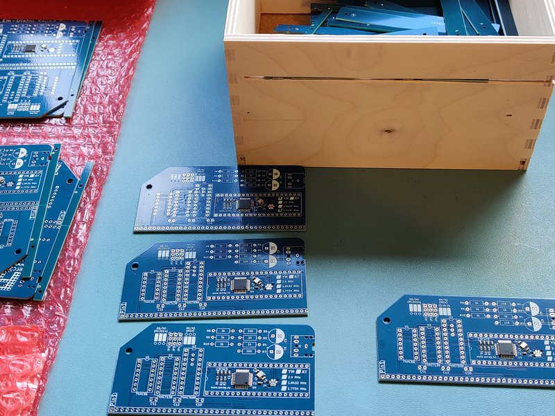
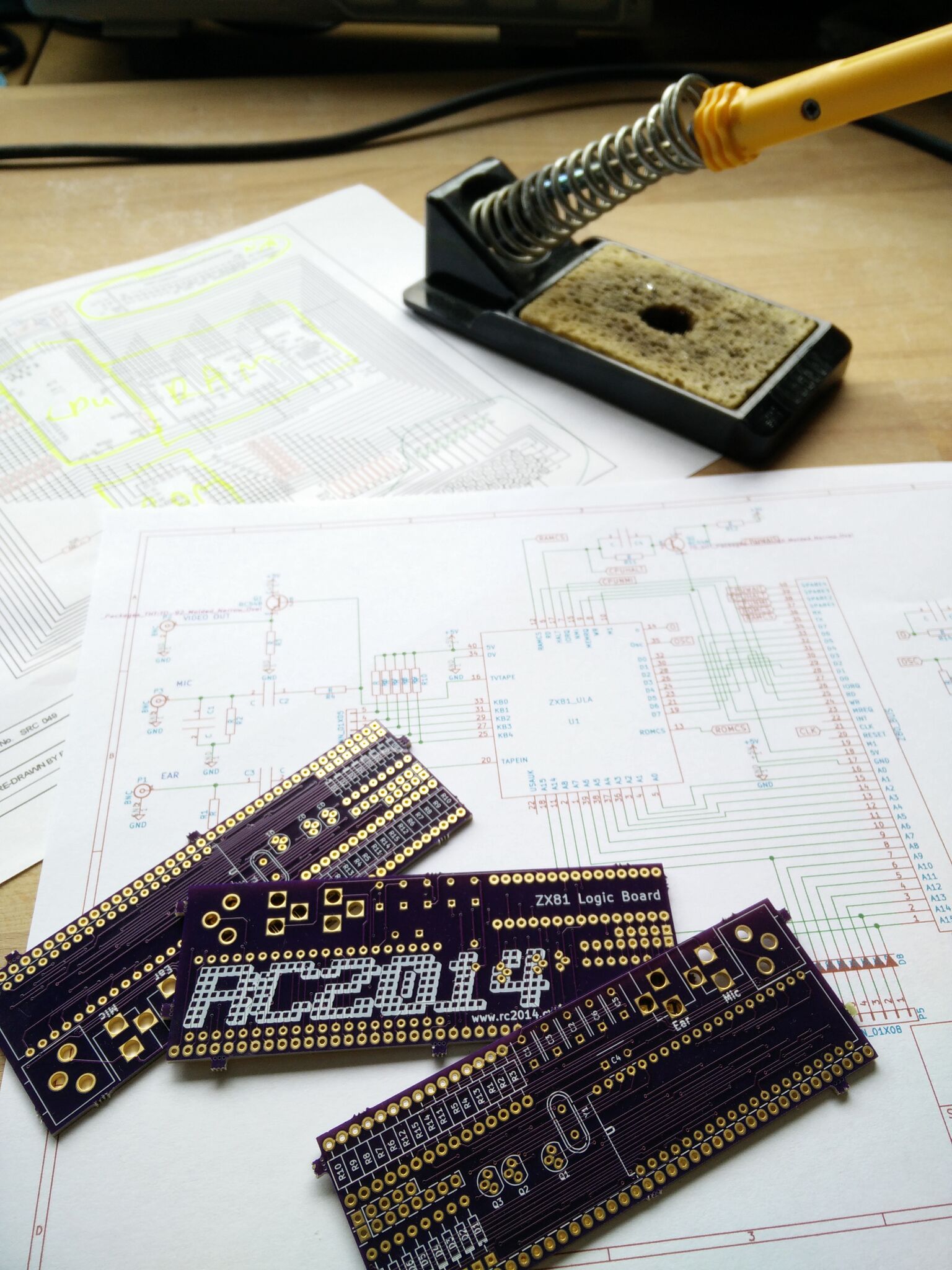
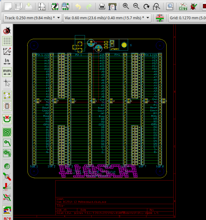
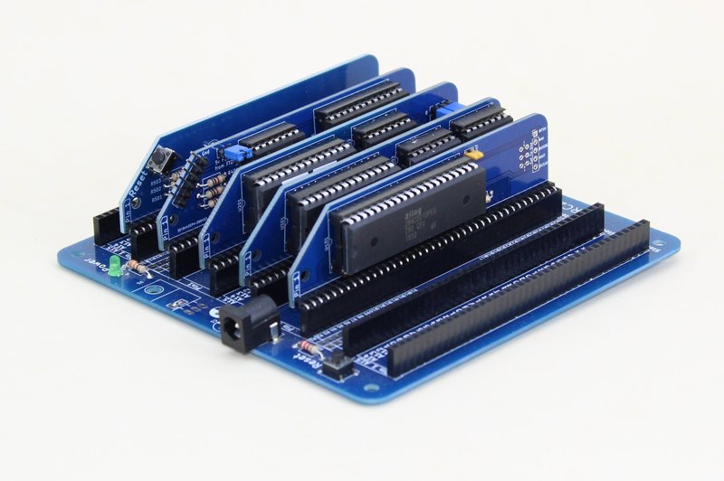
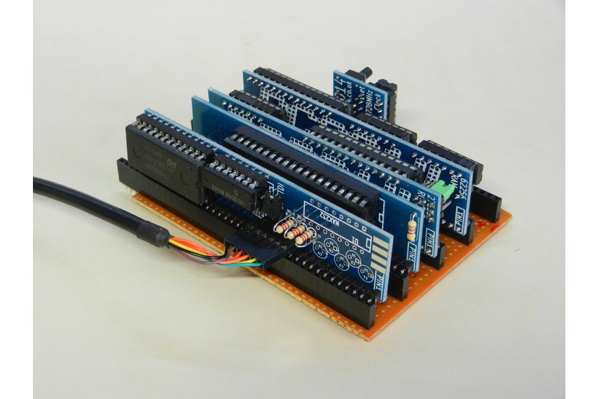
Part of the challenge was to get the PCBs designed and manufactured. I used OSHPark which meant I had 3 of each board. Luckily the designs worked and no serious modifications were needed (although a hammer was required to fit the header pins). You can read about the boards arriving here https://rc2014.co.uk/791/retro-challenge-pcbs-arrived-and-built/
Of the three sets of PCBs I had made, one set was used to build my original RC2014. Obviously. Another set was traded with John Fletcher for an original unpopulated Jupiter Ace PCB (See https://sowen.com/995/ace-adventures-on-jupiter/), and the feedback from that made me wonder if I should get some more made in case anybody else wanted to build their own RC2014.
So, what about the third set? It could be yours!


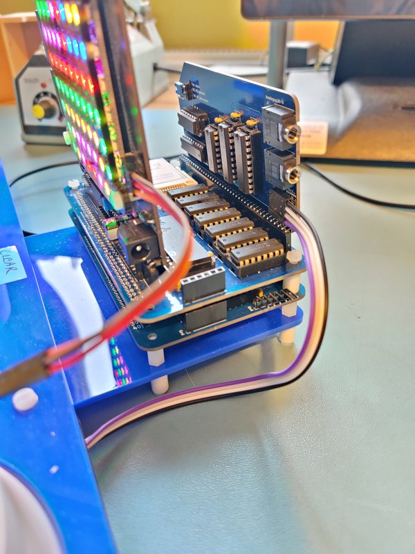
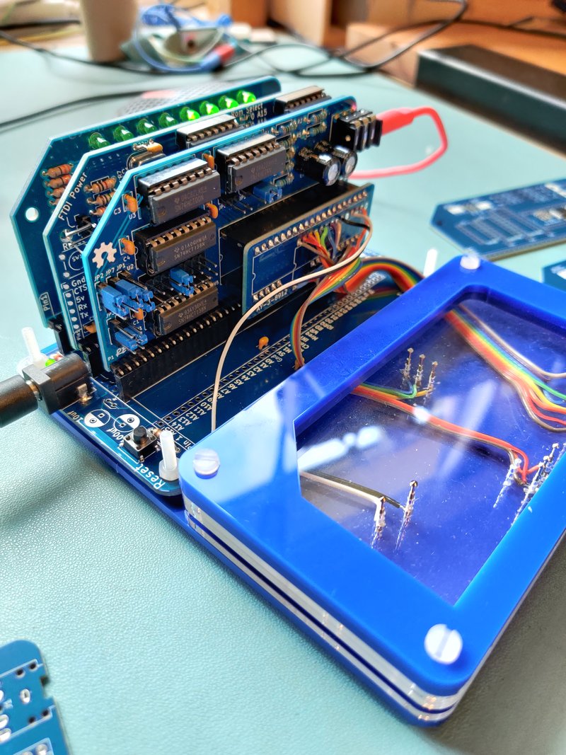
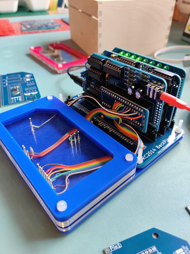
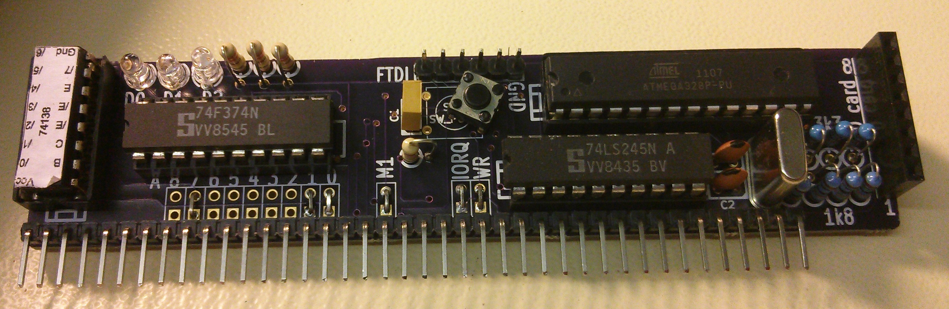
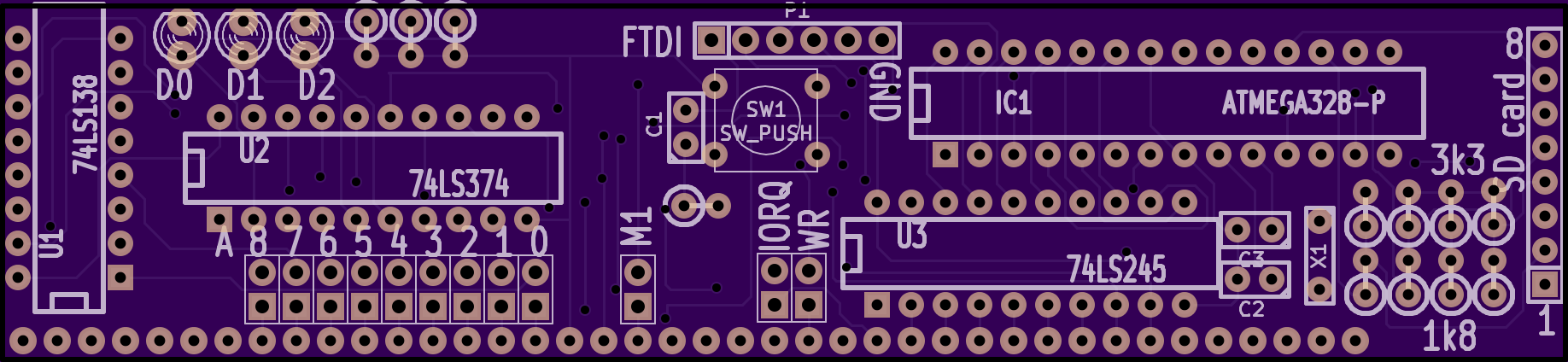
That’s right. In addition to the RC2014 Classic II kit, I will be giving away the final set of the original RC2014 PCBs to the lucky winner. Well, the original 32k RAM, Pageable ROM, Serial I/O and clock/reset module. The CPU module is a later one which the PCB manufacturer screwed up and didn’t put the silkscreen on the back! And I will throw in an original Digital I/O PCB too. As well as some stripboard.
Everything needed to complete the build is part of the Classic II kit. So when you receive your prize, you will need to decide if you want to build it as a Classic II, or go old school and make the most authentic RC2014 there is.
Not sure if I should put some legal disclaimer here or whatever. The winner will be chosen by the Retro Challenge organisers. I will post out the Classic II kit along with the original RC2014 PCBs mentioned above to the winner within a month of the winner being announced. This includes free international shipping if you are outside of the UK. No cash alternative is offered. Neither myself or the organisers of Retro Challenge can be held liable if you end up starting a new career based on your competition entry.