The modular nature of the RC2014 Pro, along with the vast array of colours that PCBs are available in these days has made me consider building a kit with all the colours of the Pride flag for quite some time. When it came down to it though, the colour choices were actually too limited. So I could either give up, or make the Pride Flag with the wrong colours… or find another solution.
Skip ahead to the tl;dr section if you want to jump past the theory, testing, and reasoning, and just want to see the process and settings I settled on.
Visit z80kits.com during June 2023 to buy an RC2014 Pro Pride or an RC2014 Zed Pro Pride. They are limited edition and raise money for two great Trans and LGBTIQ charities.
I started to search for different printing techniques and dye sublimation kept on cropping up, but mostly for things like mouse mats, t-shirts and mugs. After looking closer, I wondered if it was possible to use for PCBs. There are a few articles that seem to cover this, but they generally revolve around dye sublimation to make the mask to etch a PCB – and I didn’t want to go down that route! I eventually found an article by Ben Everard in Hackspace magazine which has a proof of concept. That was enough for me to dive deeper.
So What Is Dye Sublimation?
In scientific terms, Sublimation is the transition of a substance directly from a solid state to a gas state. It does not pass through the usual liquid state and only occurs at specific temperatures and pressures. The ink used for the process has this property, however, most inkjet printers cannot use this ink as they have a small heater on the print head. There are two types of printers that can be used for dye sublimation ink; dedicated printers made by Sawgrass which are really expensive, and Epson cheap crappy ones which can be converted. As Epson printers print cold, their print head won’t prematurely vaporise the ink, and conversion kits are available. Cheap and crappy is within my budget, although once the cheap printer is paired with a conversion kit, special ink, special transfer paper and a heat press, it isn’t all that cheap. All in, it was the best part of £500 investment – but I will be able to make my own mouse mats cheaply, so maybe that isn’t too bad!
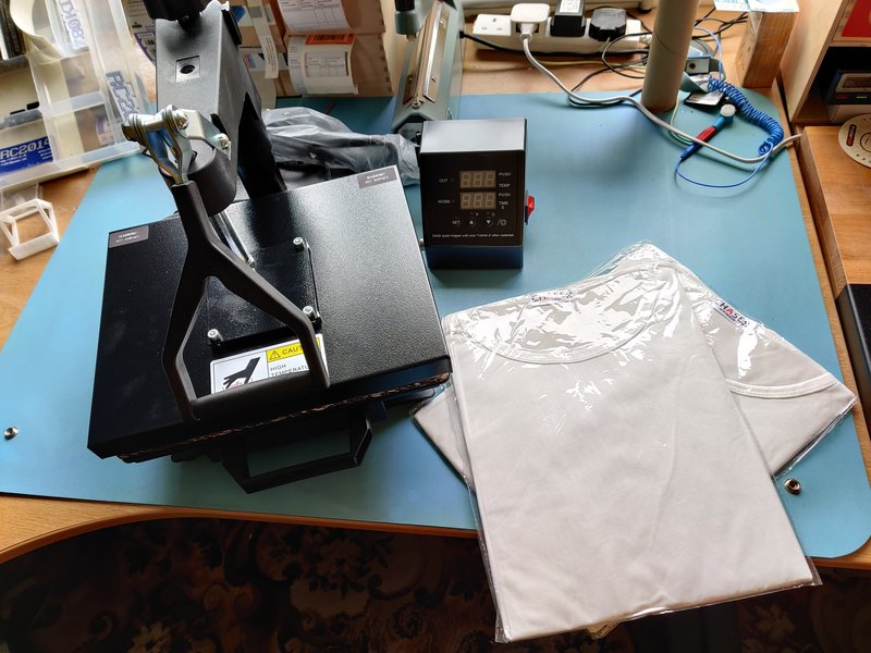
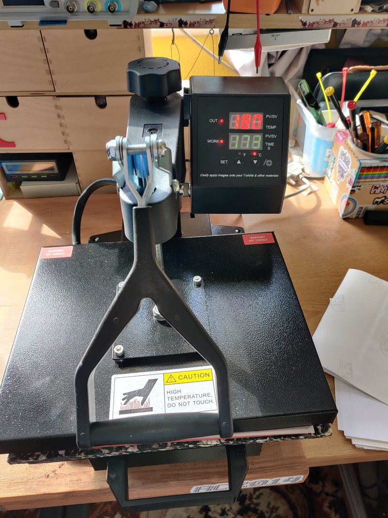
The heat press is where the magic happens. With the blank (ie mouse mat, t-shirt or PCB) in contact with the ink on the transfer paper, applying pressure and heat will turn the ink in to a vapour that embeds itself in the blank. Once cool, it remains permanently* in the blank.
Initial tests
The article from Ben Everard said that he got his PCB covered entirely in white silkscreen, and it worked. Before ordering any PCBs, I wanted to try things out with some old scrap boards. I used a colourful printer calibration page to see how things came out. Obviously trying to dye blue boards didn’t work out great with the colour, but it was a lot better than I’d expected.

The thing that I was most relieved about was that the dye does not get absorbed by the metal. Yeah, it makes sense when I think about it, but a worry was that I’d have to mask off every component hole or else design the print around the holes and line it up super precisely. But that wasn’t a worry.
Even more important was that I was able to solder to the board and that the dye wasn’t conductive. More testing and things were looking good.
I had a couple of scrap boards with white solder resists, but the colour didn’t seem to work out too great.
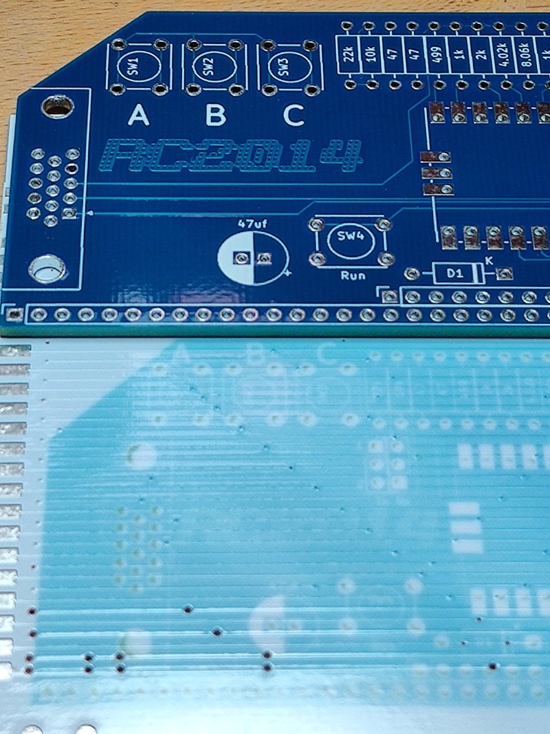
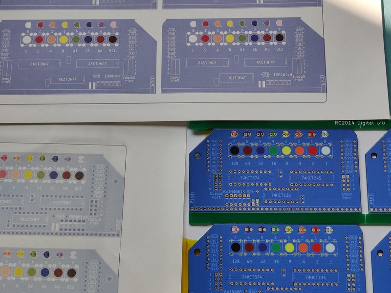
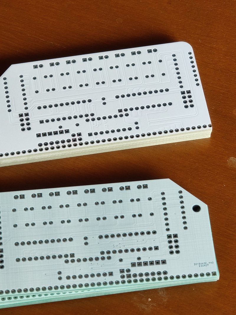
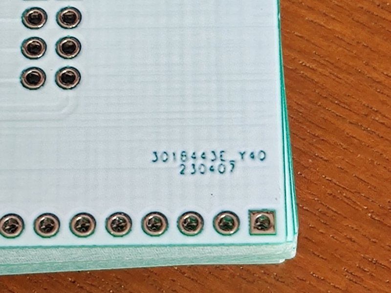
Here a real PCB is compared to a printed image of that board on to white solder resist. It has taken the dye, but really not very deeply. To test things properly, I needed some boards specifically for running tests like this. So I ordered some boards each with white solder mask and no silkscreen and some that were totally covered on both sides by silkscreen. (Fun fact: I paid to have the batch number removed on the one with no silkscreen, but I figured there was no need for that one the one which was 100% silkscreen. Turns out I was wrong!).
After exporting the original silkscreen layer from KiCad in to Inkscape I set up some different colours and tried 8 different variations between the two types of board
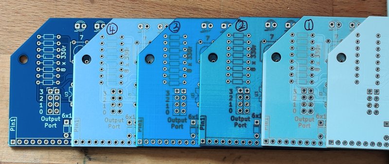
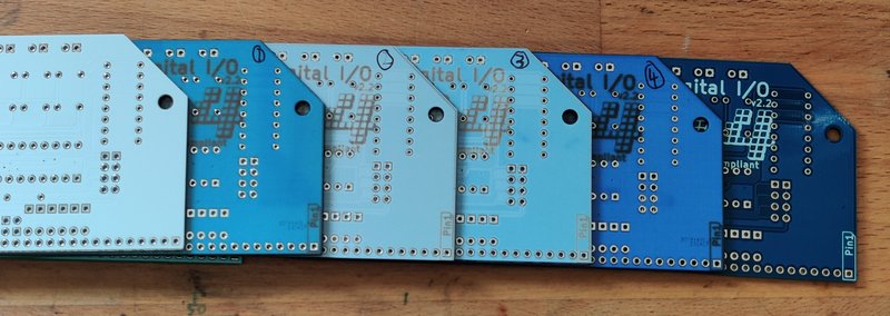
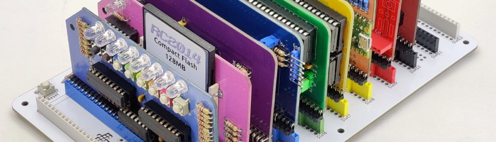
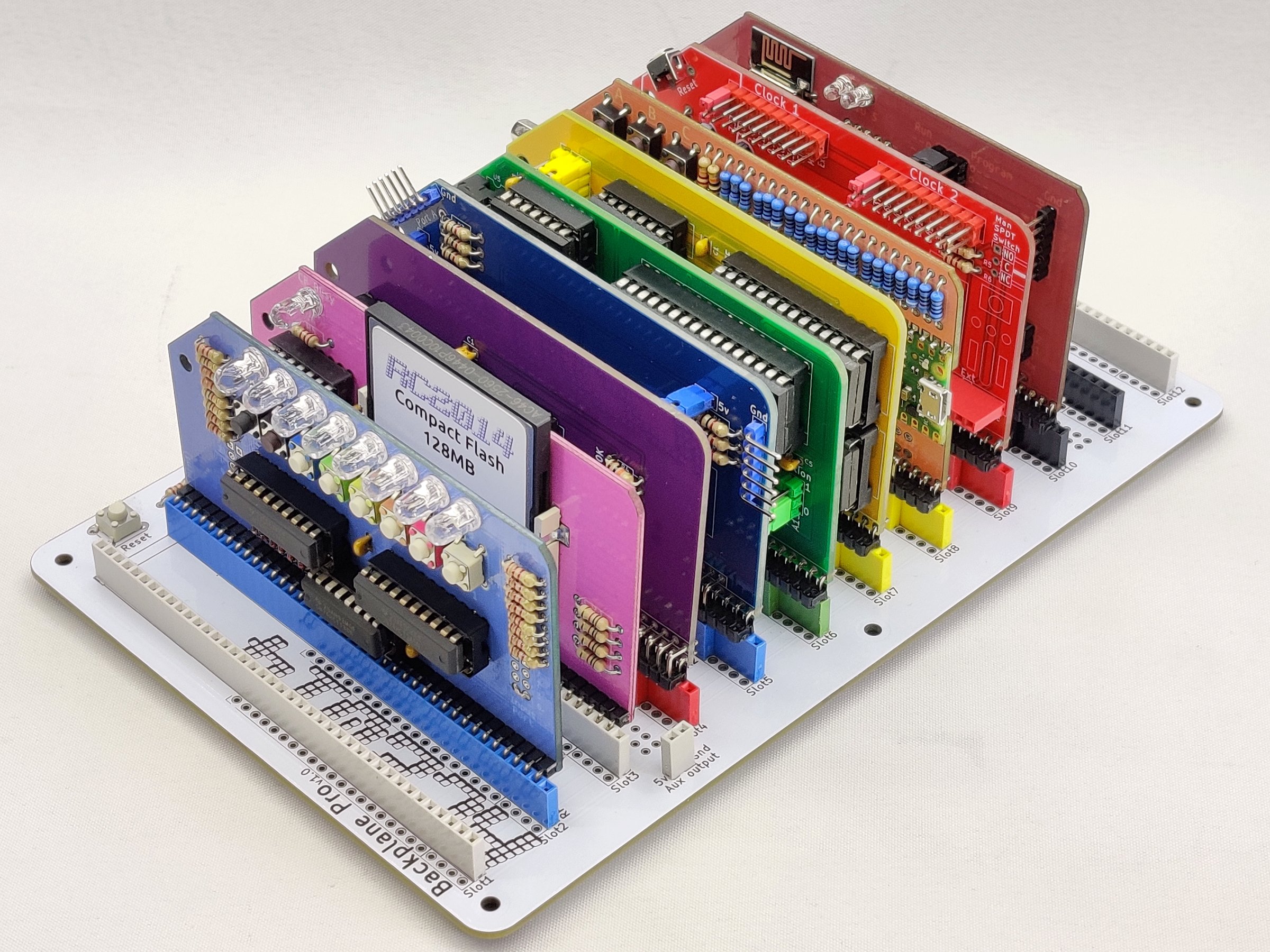
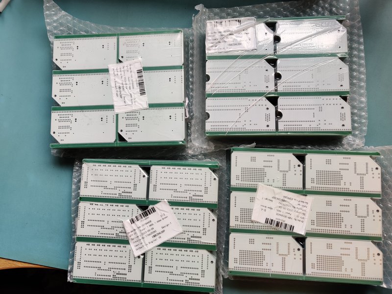
This confirmed my suspicions that the solder resist only boards had a sharper image, but they didn’t take the colour anywhere near as well as the ones covered entirely with silkscreen. As the entire motivation behind the RC2014 Pride was colour based I now had a plan. 100% silkscreen coverage for the 4 modules that JLCPCB didn’t offer the colours for; Digital I/O (light blue), Compact Flash (pink), Pi Pico VGA (Orange) and ESP8266 Wifi (brown). Of course, for the full pride flag, there should also be a black module too – however, I was able to source all of my ICs in black, so the representation is there!
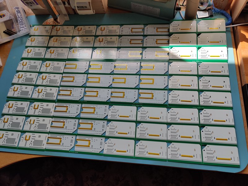
To make efficient use of the dye sublimation paper and heat press bed size I decided to panelise the boards in a 2×3 grid. The KiKit plugin for KiCad does a great job of this once you’ve dialled your settings in right (Spoiler: I didn’t quite dial them in right, and there’s a very slight lip on the top where the 45 degree and radiused corner meet the top. Sorry)
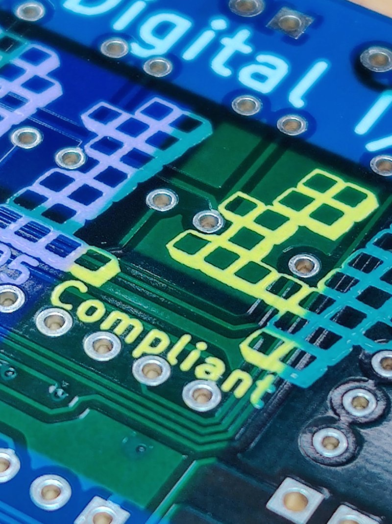
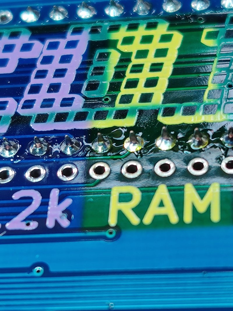
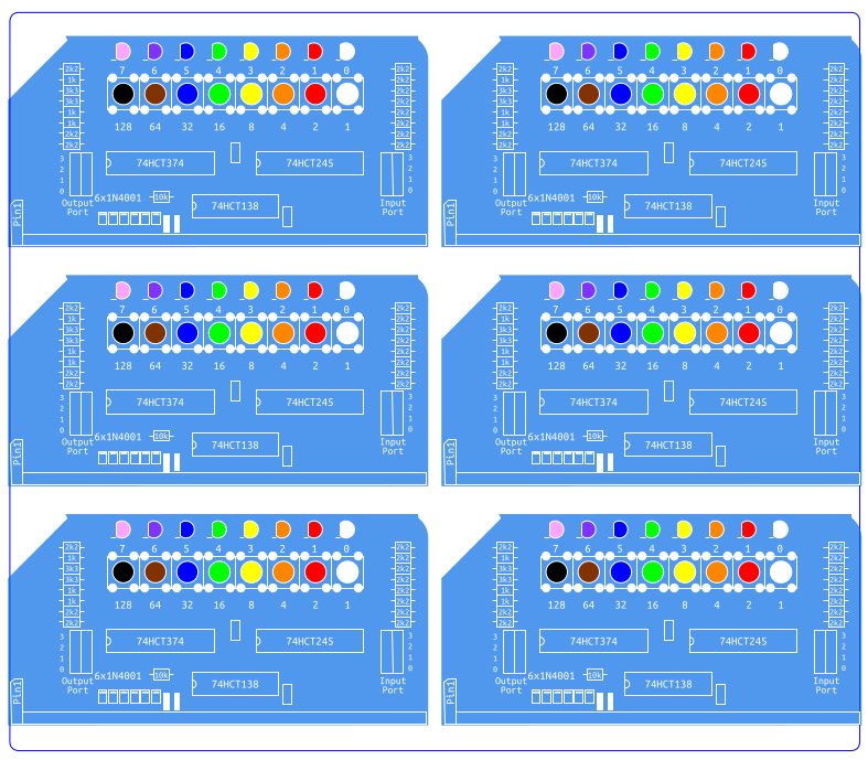
The original silkscreen layer and edge cuts from the panels was exported from KiCad in to Inkscape. From here I created a new layer above the imported layer and from here I could trace around the PCB shape and make my own artwork for it without being constrained to a single colour, font or any of the KiCad limitations. The Digital I/O module has the best representation of colour use, indicating which LEDs and switches go where. However, every board got its own bit of design flair.
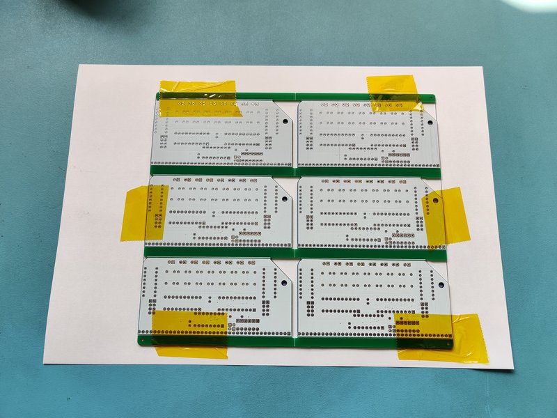
With the printer set to high quality print, slow speed and mirrored, this is then printed to the transfer paper. The PCB panel needs to be aligned very carefully and held down with Kapton tape before going in the heat press, sandwiched between 2 sheets of Teflon. Trial and error on the settings earlier suggested that 180’C and 180 seconds worked best.
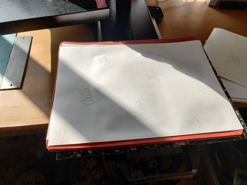
Here you can see an unused printed sheet at the top, a used sheet on the left and the dyed PCBs on the right. The colours on the unused transfer sheet are not representative of the final colour, but a .ics (image correction setting) file specifically for this ink and paper combination takes care of this and prints what is needed to get the colour you expect. You can see that some dye is left on the sheet after it has been used. Printing on to more absorbent items like mouse mats or t-shirts there is almost nothing left on the transfer sheet.
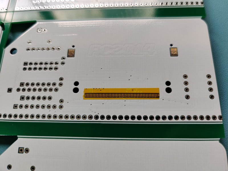
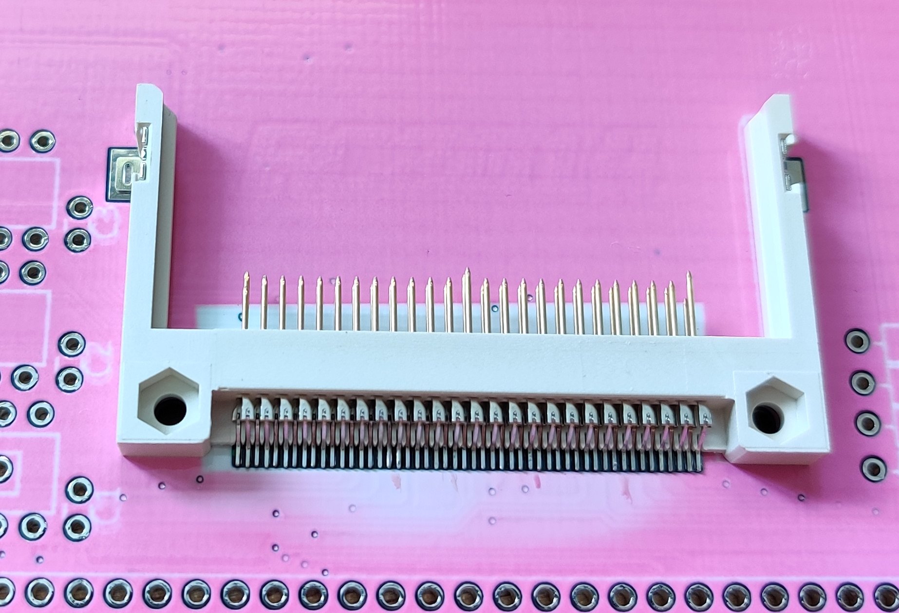
When I did the Compact Flash Module though, I encounter two big problems. When I supply the CF Modules I solder the surface mount socket beforehand as some people struggle with the 50 pin fine pitch connector. I use solder paste and a stencil, then a hot plate and hot air to reflow it.
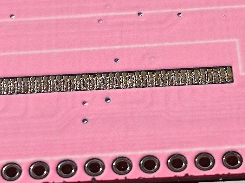
Because the dye does not penetrate the plated pads, I assumed (wrongly) that this would be fine. However, I found it impossible to get the solder paste to stick to the pads. I don’t know exactly why this is, but I assume that the heat press somehow damages the plating. It may work better with ENIG plating, although I haven’t tested this.
I did find that a strip of Kapton tape fixed this problem, although it does add extra cost an labour to each board.
The other problem is heat. Using a MHP30 hot plate at 250’C under the board will leave a white 30x30mm square on the back where the dye has evaporated! Using hot air from above will evaporate the dye too!
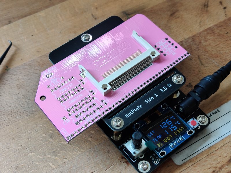
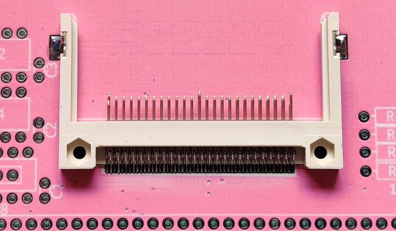
The solution I found was to use a combination of a hot plate set to 125’C to pre-warm the board then the hot air only needs to spend a few seconds from above which is enough to flow the solder but only produces minimal evaporation around the socket. It isn’t ideal, but this part is hidden deep inside the RC2014 so isn’t exactly an eyesore!
The Pi Pico and ESP8266 modules are wide pitch surface mount parts, and although these seem to flow just fine with a regular soldering iron, I have played it safe and Kapton Taped over those connections too before going through the dye sub process. It adds quite a bit of time to the process, but feels important.
However, if you were doing a modern PCB with all surface mount parts then I don’t think it is feasible to use dye sublimation. Masking off every pad would be a nightmare, and there’s no way it would survive a reflow oven. So this isn’t a miracle solution that will give everybody gloriously colourful PCBs :-(
Another issue I came across was ghosting of the text. If you look at the first CF socket photo you might spot that the text isn’t too clear, although the lines are fine. The artwork was created in Inkscape on a Linux machine, but due to printer driver issues, I printed from Inkscape on a Windows laptop. I’m not exactly sure, but I suspect that there’s some kind of font incompatibility between the two machines. The workaround for this is to export as a PDF on the Linux machine with the “Convert Text To Path” option set. This PDF can then be printed from the laptop from Inkscape and the text is fine. I think this is just an issue with my setup and not anything inherently wrong with dye sublimation.
tl;dr Here’s How _I_ do it
- Design the PCB in KiCad as normal, then cover the front and back with a filled in rectangle of silkscreen. Send this to JLCPCB to have the boards made
- Remove the rectangles and export the front and back silkscreen layers with edgecuts to PDF file
- Import the PDFs in to Inkscape. Add another layer above and use this to trace your board edge, component layout and text as you wish. Different fonts and colours and images can all be added here if required.
- I exported this to another PDF then used Inkscape on a different machine to print this (this should be a redundant step though). Printed using high quality setting, mirrored and with fast mode turned off. Separate pages are printed for the front and back of the board.
- Epson W2010 wireless printer has been converted to dye sub printing with a kit from City Ink Express, using their ink and paper
- The white PCBs are prepared with Kapton tape over surface mount pads. Then the board is laid over the back image, aligned very carefully and held in place with Kapton tape.
- The pre-heated heat press is set to 180’C. The PCB is set face down with the printed page on top, and a sheet of Teflon over the top. This is then pressed for 3 minutes then removed.
- When cool, the PCB is removed from paper, flipped over and attached to the front image sheet and the heat process is repeated.
Problems and lilmitations
Whilst this offers a lot of possibilities with PCB design, it is far from perfect. Firstly is the upfront cost of the equipment needed to print and transfer the design. It is a very labour intensive process which uses specialised ink and paper, so these costs need to be taking in to account too. Alignment needs to be accurate too (unless you have a design that doesn’t need to be aligned). The image is not pin sharp, and there is a certain amount of feathering around edges due to the silkscreen, so fine details may not work too well. And lastly, the surface mount limitation is going to make it a non-starter for a lot of projects. But, with all those points in mind, if it works for you, the possibilities are endless.


