Jig-Ulator

Sometimes an RC2014 has just one job. This one is to go Beep Whoop, Beep Beep Whoop, Beep Beep Beep Whoop! whenever a working Why Em-Ulator Sound Module PCB is put on the jig.

Jig-Ulator

Before we get to that, though, lets go back to the start and consider the Why Em-Ulator Sound Module. This is supplied to RC2014 Towers with the surface mount components assembled and the PCBs panelised. The panelisation is needed so that they will go through the assembly process at the fab house. So the first thing to do is remove the rails and separate the pair of boards.

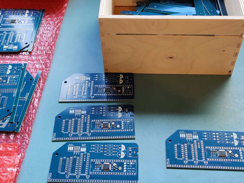
Removing the rails is made easy with a slot cut in to a wooden box. The rails are put in to the slot and a quick bend up and down detaches them from the main PCB. The discarded rails are then collected in the box. Breaking the two PCBs apart is also a simple process.

Next the micro controller needs to be programmed. The PCB has a TC2030 Tag Connect compatible programming header next to the micro controller. The programming cable has spring loaded pogo pins and some locating pins that protrude through the board. To accommodate this, a small jig (Jiglett) is used.

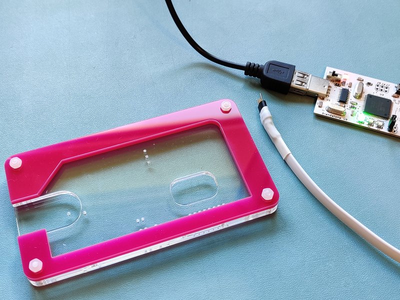
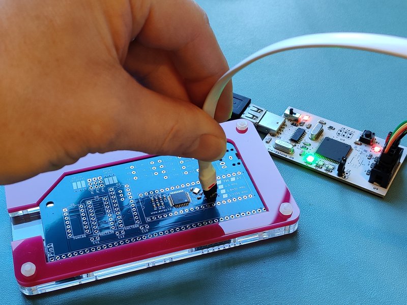
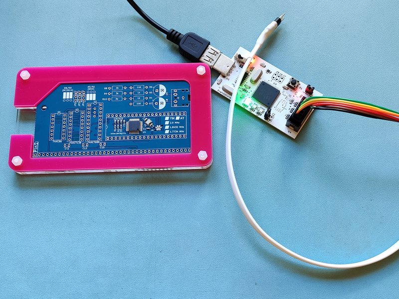
The programmer is a stand alone device which has the flash hex file, eprom hex file and fuse settings for the default Why Em-Ulator settings (YM2149 at 1.7734MHz). Other settings can be programmed manually from a laptop.

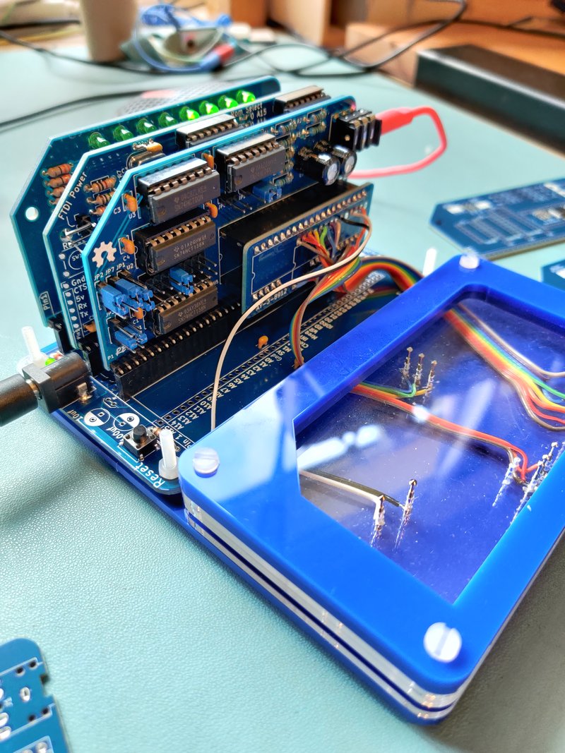
For peace of mind that the firmware has been programmed successfully, and that the assembly process was correct, it needs to be tested. This is where the Jig-Ulator comes in.

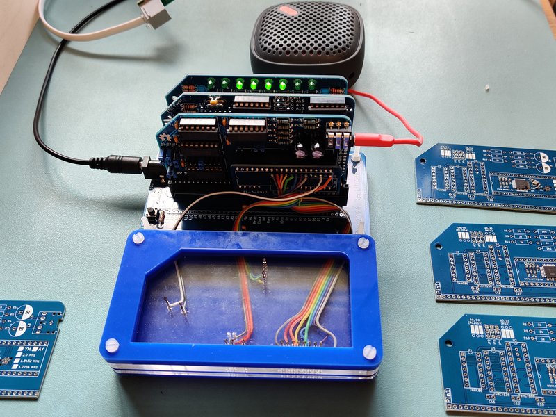
At the heart of the Jig-Ulator is an RC2014 Micro. This sits in a Backplane 5 with 3 sockets fitted. One of these sockets has a Digital I/O Module for visual feedback and the other has a Rev 5 YM2149 Sound Module with an AY-3-8910 to AY-3-8912 adapter. This adapter carries all the signals (Power, 8 data lines, Reset, BC1 and BDIR) that the Why Em-Ulator needs to operate, as well as the return path for the sound from Channel A, Channel B and Channel C. The sound module is plugged in to a speaker for audio feedback.

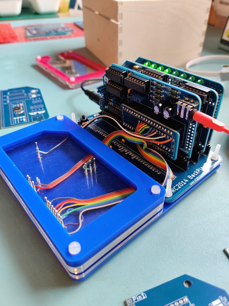
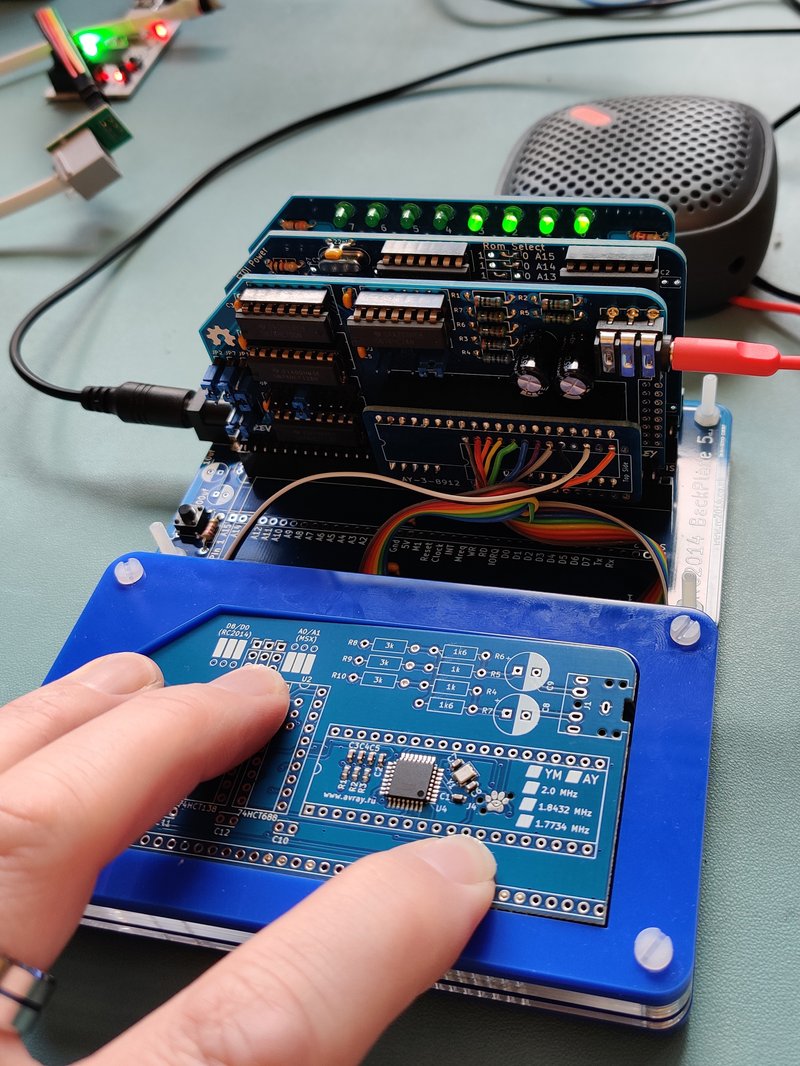
At the front of the Jig-Ulator is a bed of nails test jig made from laser cut Perspex and pogo pins. The Perspex holds the pogo pins in place, and the upper layers have an alignment cutout so that the module under test will line up perfectly with the pins. A little bit of pressure ensures that all signals make good contact.

The RC2014 Micro has some very simple test code in ROM that runs on startup and continues indefinitely. This code isn’t elegant. Nor is it particularly efficient. And it certainly isn’t an example of how to write good Z80 assembly code. However, it has one job, test the module, and it does that well.

All of this only takes up a couple hundred bytes of the 8k ROM. It can surely be optimised to take up less space. Alternatively, the calls can be unrolled to take up more space but without needing any RAM for the stack.

            .ORG    $0000 
REG         EQU     $D8 
DAT         EQU     $D0 
START:               
            NOP      
            NOP      
            DI       ; disable interrupts
            LD      hl,$9000 
            LD      sp,hl ; set up stack
            NOP      
;set mixer reg to enable channel A
            LD      a,7 
            OUT     REG,a 
            LD      a,62 
            OUT     DAT,a 
            LD      a,15 
            OUT     0,a ; set DIO lights right

;set channel A to max volume
            LD      a,8 
            OUT     REG,a 
            LD      a,15 
            OUT     DAT,a 

;output 2 note to channel A
            LD      a,0 
            OUT     REG,a 
            LD      a,128 ;low note
            OUT     DAT,a 
            CALL    delay 
            LD      a,255 ;high note
            OUT     DAT,a 
            CALL    delay 

;decremental tone
            LD      a,0 
            OUT     REG,a 
            LD      b,255 
            CALL    ALOOP 

;set mixer reg to enable channel B
            LD      a,7 
            OUT     REG,a 
            LD      a,61 
            OUT     DAT,a 
            LD      a,$F0 
            OUT     0,a ; set DIO lights left

;set channel B to max volume
            LD      a,9 
            OUT     REG,a 
            LD      a,15 
            OUT     DAT,a 

;output 4 note to channel B
            LD      a,2 
            OUT     REG,a 
            LD      a,255 ;low note
            OUT     DAT,a 
            CALL    delay 
            LD      a,128 ;high note
            OUT     DAT,a 
            CALL    delay 
            LD      a,255 ;low note
            OUT     DAT,a 
            CALL    delay 
            LD      a,128 ;high note
            OUT     DAT,a 
;decremental tone
            LD      a,2 
            OUT     REG,a 
            LD      b,255 
            CALL    ALOOP 

;set mixer reg to enable channel C
            LD      a,7 
            OUT     REG,a 
            LD      a,59 
            OUT     DAT,a 
            LD      a,60 
            OUT     0,a ; set DIO lights middle

;set channel C to max volume
            LD      a,10 
            OUT     REG,a 
            LD      a,15 
            OUT     DAT,a 

;output 6 note to channel C
            LD      a,4 
            OUT     REG,a 
            LD      a,128 ;low note
            OUT     DAT,a 
            CALL    delay 
            LD      a,255 ;high note
            OUT     DAT,a 
            CALL    delay 
            LD      a,128 ;low note
            OUT     DAT,a 
            CALL    delay 
            LD      a,255 ;high note
            OUT     DAT,a 
            CALL    delay 
            LD      a,128 ;low note
            OUT     DAT,a 
            CALL    delay 
            LD      a,255 ;high note
            OUT     DAT,a 
;decremental tone
            LD      a,4 
            OUT     REG,a 
            LD      b,255 
            CALL    ALOOP 


;turn sound off
            LD      a,7 
            OUT     REG,a 
            LD      a,63 
            OUT     DAT,a 
            LD      a,0 
            OUT     0,a 
            CALL    DELAY ; wait....
            CALL    DELAY 
            CALL    DELAY 
            CALL    DELAY 
            CALL    DELAY 
            CALL    DELAY 
            CALL    DELAY 
            CALL    DELAY 
            CALL    DELAY 
            CALL    DELAY 
            CALL    DELAY 
            CALL    DELAY 
            JP      START ; and start all over again


            EI       ; enable interrupts
            RET      ; which will never get to. But helpful for debugging RAM based versions of the code
SHORTDELAY:          
            PUSH    hl 
            PUSH    af 
            LD      hl,1000 
            JP      DELLOOP 

DELAY:               
            PUSH    hl 
            PUSH    af 
            LD      hl,$ffff 
DELLOOP:             
            DEC     l 
            JP      nz,DELLOOP 
            DEC     h 
            JP      nz,DELLOOP 
            POP     af 
            POP     hl 
            RET      

ALOOP:               
            LD      a,b 
            OUT     DAT,a 
            CALL    SHORTDELAY 
            DEC     b 
            JP      nz,ALOOP 
            RET      


After starting up, interrupts are disabled and a stack area is defined. Then it makes a Beep-Boob on channel A, whilst turning on the right 4 LEDs on the DIO module, then plays a Whoop noise. It then does this again on Channel B, but with a Beep-Boop-Beep-Boop and illuminating the left 4 LEDs. And finally, it does this again on Channel C, but with a Beep-Boop-Beep-Boop-Beep-Boop and the middle 4 LEDs. Slight pause and back to the start.

The whole thing only takes a few seconds to confirm that everything is working as it should.

Retro Challenge 2017/10 Testing

The initial testing of the ESP8266 board with the RC2014 was pretty good, and fundamentally it worked.  However, it wasn’t quite right, and I suspected that the problem was to do with CR or LF.

The code I was using was found here; https://github.com/tzapu/WebSocketSerialMonitor (Thanks Tzapu!).  It uses web sockets, and allows an external web page to connect through to the ESP8266.  So, by going to http://tzapu.github.io/WebSocketSerialMonitor/ and connecting to ws://x.x.x.x:81/ws (where x.x.x.x is my external IP address and a firewall rule is set up to forward port 81 through to the internal address of the ESP) it will display everything the ESP receives on its Rx pin.  Well, almost everything, but not quie everything.

If, for example, I did a directory listing which was 2 full lines and a little bit more on the 3rd line, only the first 2 lines would show up.  If I’m playing Zork, sometimes it would show the whole chunk of text as it came in, other times it would miss the last line.

The code itself is fairly easy to read, although the complicated web sockets stuff is hidden away in libraries.  This is the part of the routine that reads the serial input until it detects a CR (the ‘\n’ part), where upon it then sends the line;

void serialEvent() {
  while (Serial.available()) {
    char inChar = (char)Serial.read();
    if (inChar == '\n') {
      stringComplete = true;
      return;
    } else {
      inputString += inChar;
    }
  }
}

I figured that adding a check for a LF would do the job;

if (inChar == '\n' || inChar == '\r') {

But, sadly, it didn’t.  If anything, it made it worse.  So, instead, I tried just reading a set amount of characters (10 initially) and sending them regardless of a CR or LF, but that didn’t work either.  When I got it to send every character without checking, it worked much much better, although if I sent a very large chunk of text it would miss random bits of it.

So, the problem seemed to be speed related.  The checking for CR was a nice idea by the original author, but it wasn’t something I needed, so time to strip out all the surplus code.  It went from this;

void serialEvent() {
  while (Serial.available()) {
    char inChar = (char)Serial.read();
    if (inChar == '\n') {
      stringComplete = true;
      return;
    } else {
      inputString += inChar;
    }
  }
}


void loop() {
  serialEvent();
  if (stringComplete) {
    
    String line = inputString;
       // clear the string:
    inputString = "";
    stringComplete = false;

    //line += '\n';
    webSocket.broadcastTXT(line);
    Serial.println(line);
  }
  webSocket.loop();
}

to this;

void serialEvent() {
  while (Serial.available()) {
    char inChar = (char)Serial.read();
    inputString += inChar;
  }
}

void loop(){
  serialEvent();
  webSocket.broadcastTXT(inputString);
  inputString="";
  webSocket.loop();
}

Much simpler, and it seemed to work perfectly!

All the testing up until this point was done either on my laptop or mobile.  Although they are on the same wifi network as the ESP, it’s connecting out to an external web page before coming back in, so it should be a reasonable test.  But there’s nothing like real people connecting in to really see if it works.  So, I put a shout out on Twitter, and on Saturday evening, 4 willing volunteers sat there watching me do random things on the RC2014.

Feedback was pretty good, and it all seemed to work as expected.  Thanks Thilo for this screenshot;

I messed about with simple programs in BASIC, directory listings, and the opening moves in Zork, with success.  In a moment of madness, I fired up Wordstar.  When the RC2014 is connected to a VT100 terminal, it works great by using escape codes to set where things are on the screen and what colours are used.  However, these escape codes don’t render at all well on the web sockets interface.  Thanks Dave for showing my just how bad it looked!

So, yes, I should have known that Wordstar would be pushing it a bit far.  But otherwise, I was very pleased with the performance.

The biggest problem I had, though, was that of feedback when interacting with the “audience”.  I could type short sentences in to Zork that the viewers would see and understand, even if the Zork engine couldn’t interpret it.  But, of course, there was no live feedback from the viewers.

I’m not sure what the solution to that will be, but it could be as simple as keeping Twitter open on my phone.  Alternatively, things like IRC or Slack could be used (although I don’t want viewers to have to jump through hoops to get connected to me).  Skype might be an option too, although, at the moment, I think it’s more likely I’ll set up a YouTube live stream and use the chat feature in that.

For those wondering about the set up that I’m using, it’s pretty much a stock RC2014 Pro with a Pi Serial Terminal and the ESP8266 prototype I built for this project.  The Pi Zero is connected via a HDMI > VGA adapter, and then to a 17″ monitor.  The keyboard is this Cherry keyboard from the last Retro Challenge.  Note that the key layout is sufficiently different from what I’m used to that typos aren’t too uncommon yet.

The laptop is there to program the ESP, and to monitor it’s output.

I am aiming to have a live run through on Friday, so that gives me a few days to look in to the feedback options.

HDMI and USB Keyboard Support

So, the RC2014 is a great little computer.  We all know that.  However, to communicate with it, it is easiest to use the serial port and hook it up to a laptop or desktop PC.  This makes detracts from the fact that it is small, portable and cheap as well as missing the point of running code on such a basic computer.  So I’ve been looking for a solution to this.

Back when this was still running on a breadboard, I hooked up an Atmel ‘328 that was connected to a keyboard and 4 x 20 LCD display.  It communicated with the RC2014 over the serial port and kind of worked ok, although 4 lines was very restrictive and the Atmel couldn’t really keep the screen running and listening at the same time.   I have thought about using a ‘328 to drive a composite output, or maybe some kind of bigger LCD panel, but nothing really struck me as just right.

That is, until the kind people at Raspberry Pi released a cheap multifunction interface device a couple of weeks ago!

2015-12-18 22.13.44

(more…)

RC2014 SD Bootloader Update

Just a quick update to about the SD Bootloader I designed a few posts ago.  Well, the PCBs have arrived and last week I took a soldering iron to one of them and gave it a quick test

One side of the board is effectively an Arduino, so without plugging it in to the RC2014, I connected up an FTDI lead and uploaded the Arduino Blink sketch.  A quick check with a multimeter and one of the pins was altenating between 5v and 0v.  So far, all good! (more…)