So, who remembers my entry for Retro Challenge in January? It was quite devoid of effort and results I think you’ll agree.
Well, this time around, I’ve taken that theme and pushed it even further! Even less effort and much less result.
Since January, I have had a few opportunities to carry on with the ZX81 Module. Because I wanted this to be a Retro Challenge project, I deliberately avoided doing any work on it, so I could save it all for October. Well, October started and I was overwhelmed with non-Retro Challenge stuff. But after a couple of weeks, I had a spare afternoon, and decided to dedicate this to the ZX81 Module!
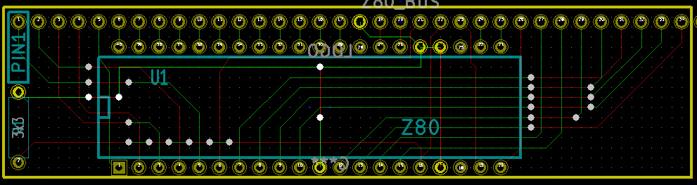
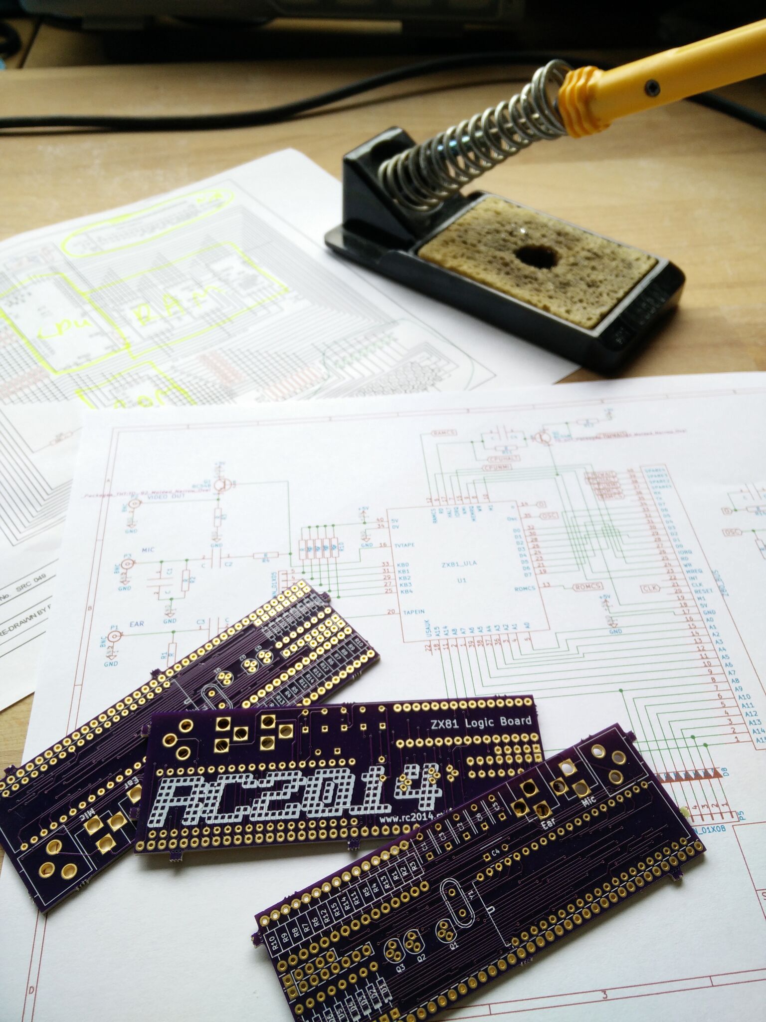
So, I dug out the PCBs I had manufactured in January and fired up the soldering iron;

Time to wrack my brains and work out what my plans had been 9 months earlier. I had failed to put any component values on the PCB, or even my Kicad schematics, so had to rifle through original ZX81 schematics to work out what these should be.
Now I knew what components I needed, it quickly dawned on me that I didn’t have very many of these at all. This didn’t deter me though. I fitted everything I had; IC socket, pin headers, some resistors and some transistors that may or may not be compatible;

And that’s about it. I have ordered the rest of the parts now, but not had an opportunity to fit them. yet.
One thing I have learned from this experience though, is that if I get any opportunity or urge to work on this, then I will seize it. Not wait until the next Retro Challenge. If I’d done work on this months ago when I had the chance, then this would more likely be a trouble shooting / tweaking / developing challenge.
One other good thing that has come out of this though, is that when I started this in January, I had a few design changes or additions required for the RC2014 for it to work. The Backplane 8 has the ability to add resistors between the CPU and the RAM. The Universal Micro Keyboard has the right connections to work with a real ZX81 or this ZX81 Module (including diodes). The CPU Module also now has BUSRQ, WAIT, NMI and WAIT pins broken out which is required for this. These changes should all make things much easier.
Despite my poor efforts this time around, I have thoroughly enjoyed seeing what everybody else has achieved with their Retro Challenge. Good work everybody else!