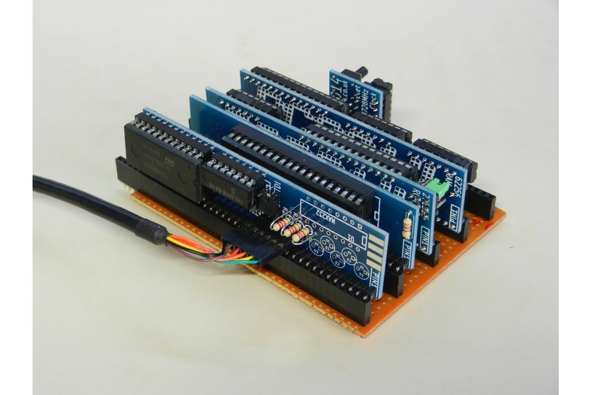
The ZX81 Module I designed in 2016 has been an example of Schrödinger’s PCB. It has sat around for 8 years in both a state of working and not working. Only when it is observed will the actual state be determined. In this wrap up post we will finally plug it in and find out.
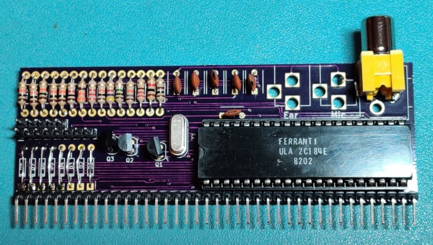
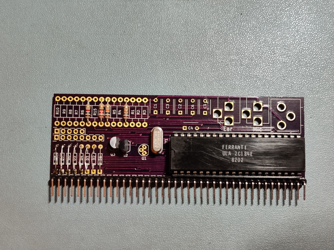
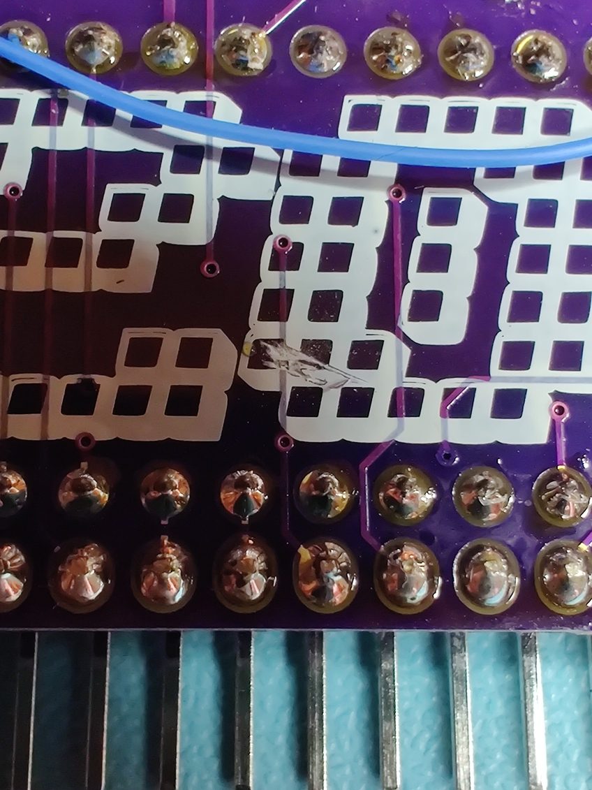
The first step was to finish assembling the board. If you remember back to the start of the month, or indeed 2016, you will have noticed that the PCB was partially assembled with 4 resistors, 2 transistors, crystal, chip socket and header pins. All the values are now on the schematic, so building up the rest of it was straightforward. I don’t know why 2016-Me only fitted 2 of the transistors. They are all the same value and I have a strip of 50 of them. I did find an error with the footprint I used for the composite jack, but this was easily fixed by turning it 90 degrees.
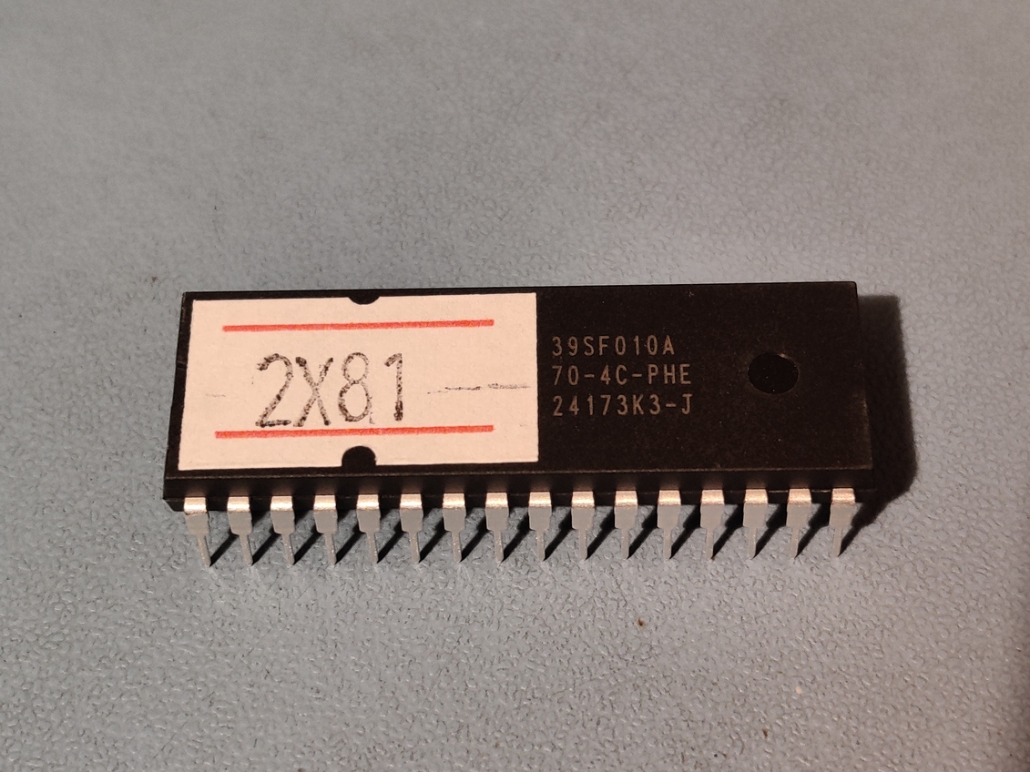
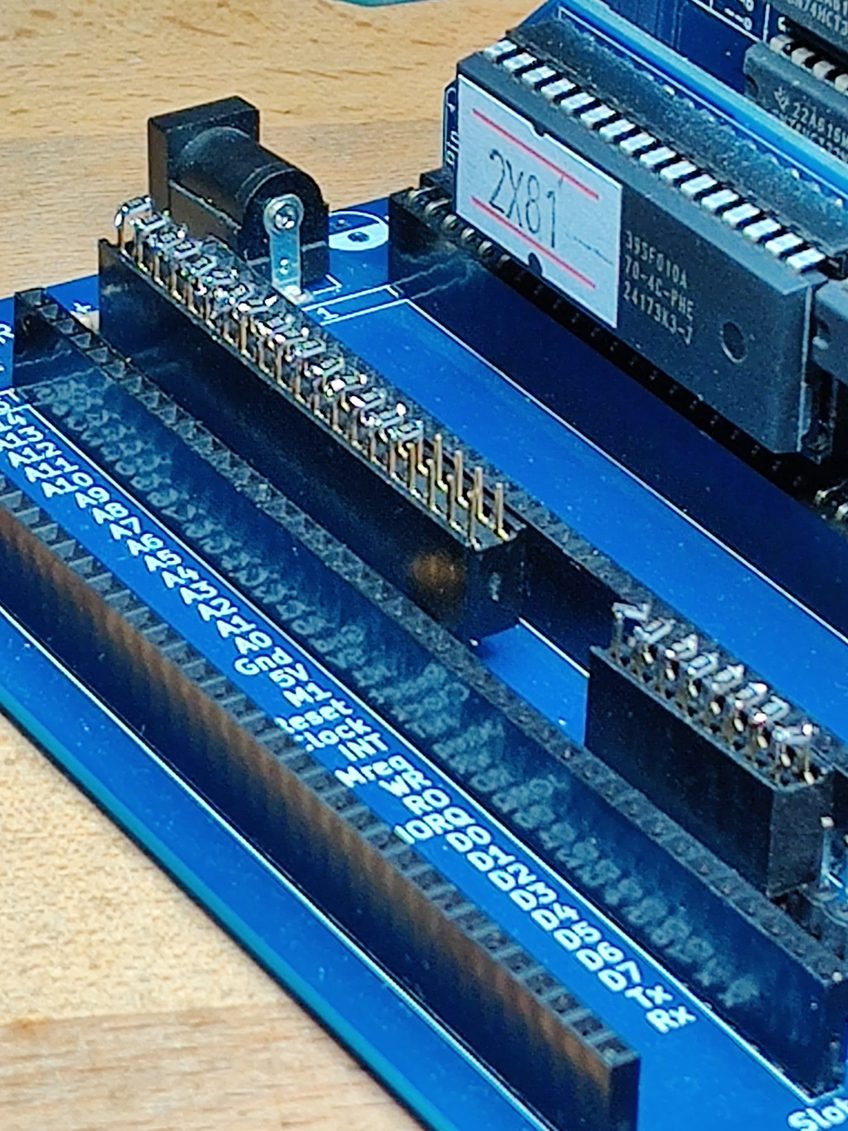
I burned a ROM with the first 8k duplicated in to the second 8k bank. Sadly my pricing gun that I use for ROM labels doesn’t have a Z, so it’ll have to be a 2X81 now :-)
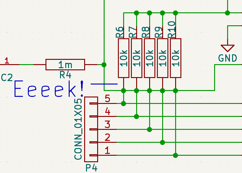
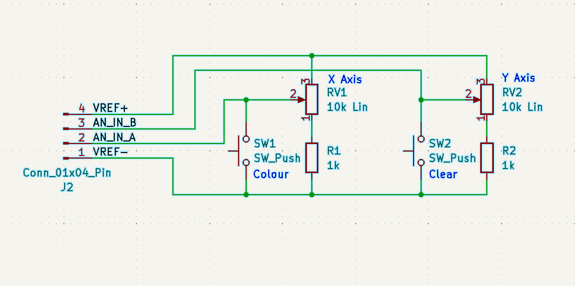
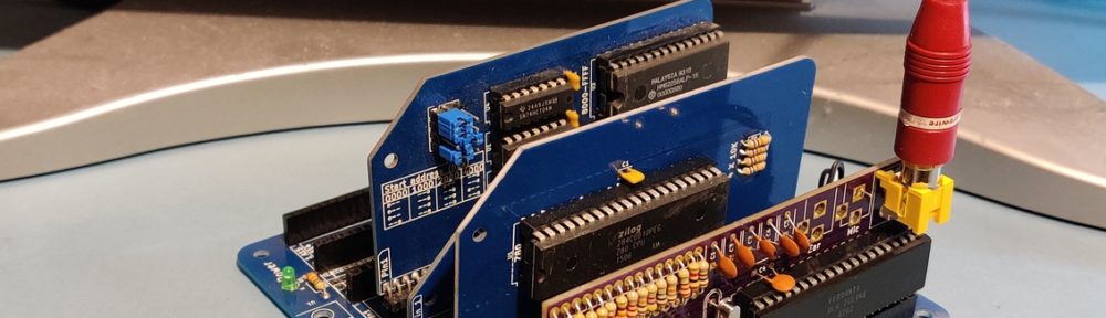
The next big dilemma was about the current limiting resistors – the green blocks on this diagram.
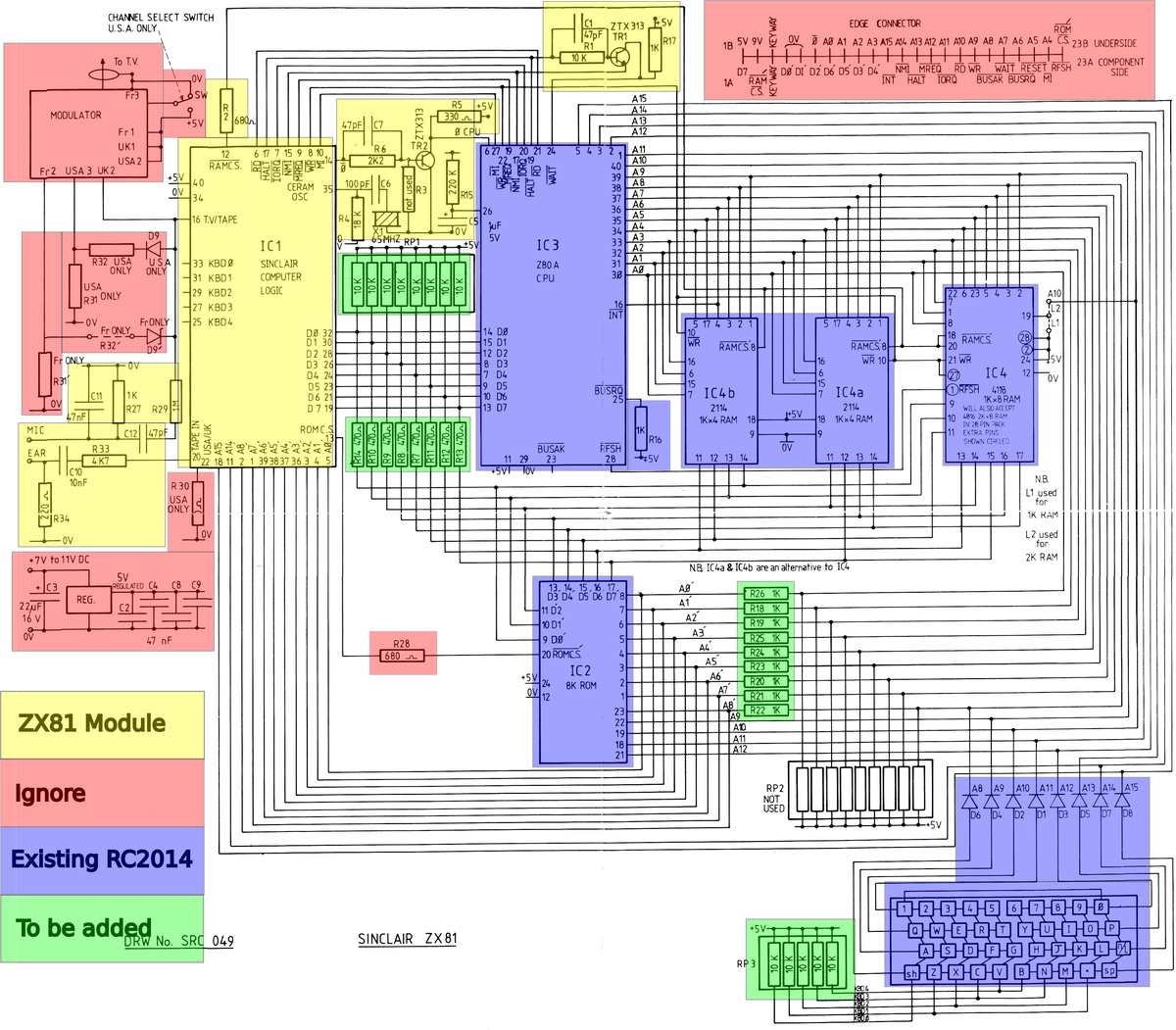
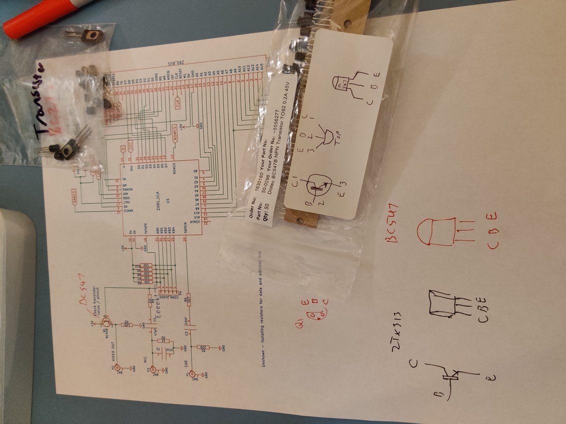
My understanding of what they are for is that they protect the components if there are conflicting values put on the bus. For example, if the Z80 was doing a write with 0xFF on the data bus, and at the same time the ROM was doing a write and put 0xFE on the bus. This situation should never happen, however, if it did, the D0 pin on the Z80 would be 5v and the D0 pin on the ROM would be 0v, so current would flow from the CPU to the ROM faster than the CPU could source it or the ROM could sink it. Having resistors in there will limit the current, and potentially save the parts.
The logic in a stock RC2014 means that there can only be one device writing to the address or data bus at any one time, so this kind of situation couldn’t crop up. However, with something like the original SD Memory Dump Module, the AVR chip was under software control. So any screwup on the software side could mean that both the AVR and another device could write to the bus. So current limiting resistors were important for that.
The ZX81 schematic confused me though. The CPU and RAM sat on one side of the address bus resistors with the ULA and ROM on the other side. But the CPU and ULA were on one side of the data bus resistors with the ROM and RAM on the other side. I do not fully understand exactly what the ULA does, but the implication is that it could mess with either bus in some way. The RC2014 backplane certainly doesn’t allow for that combination of modules with resistors between them. Rightly or wrongly, I decided to separate the ULA from the ROM, RAM and CUP via resistors.
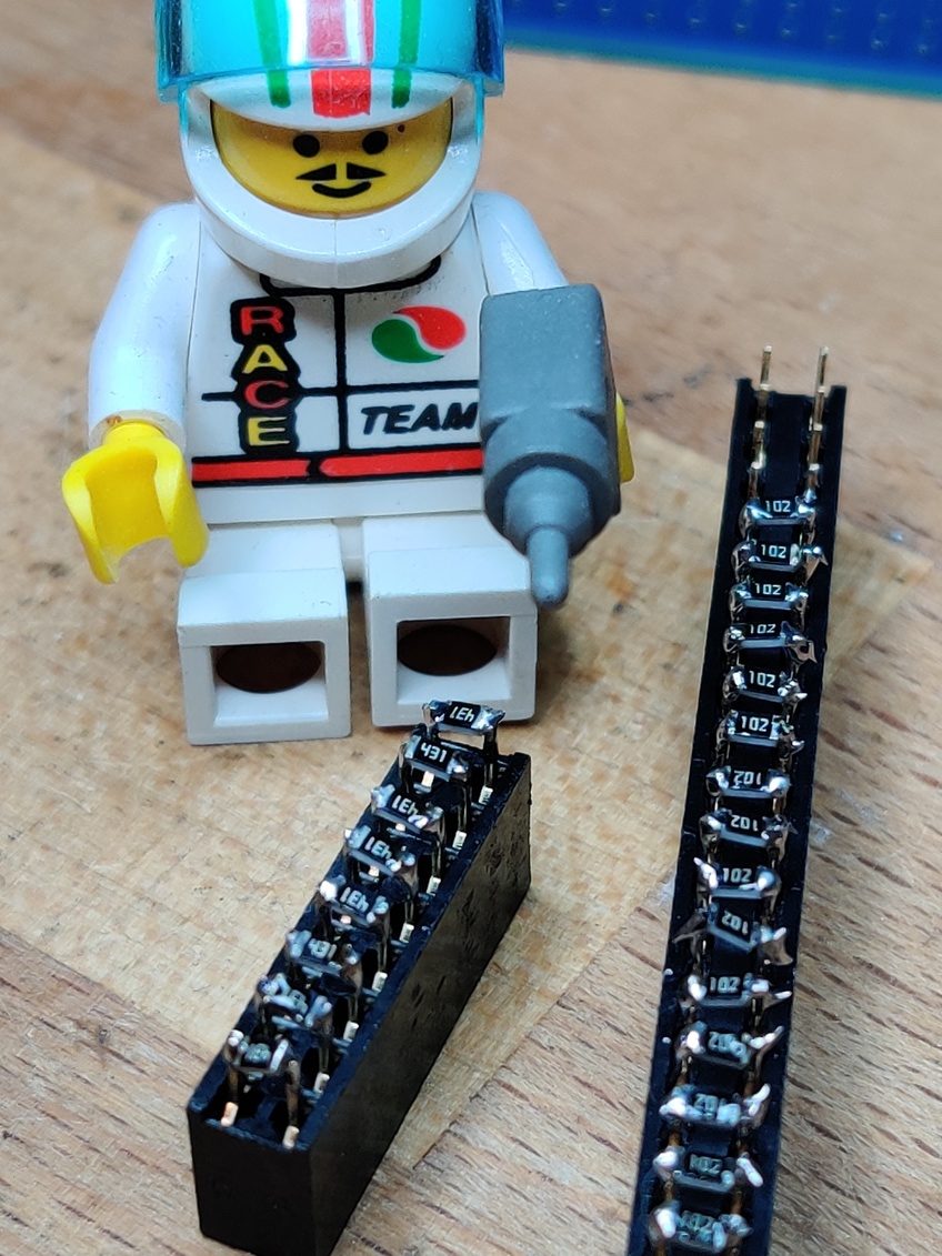
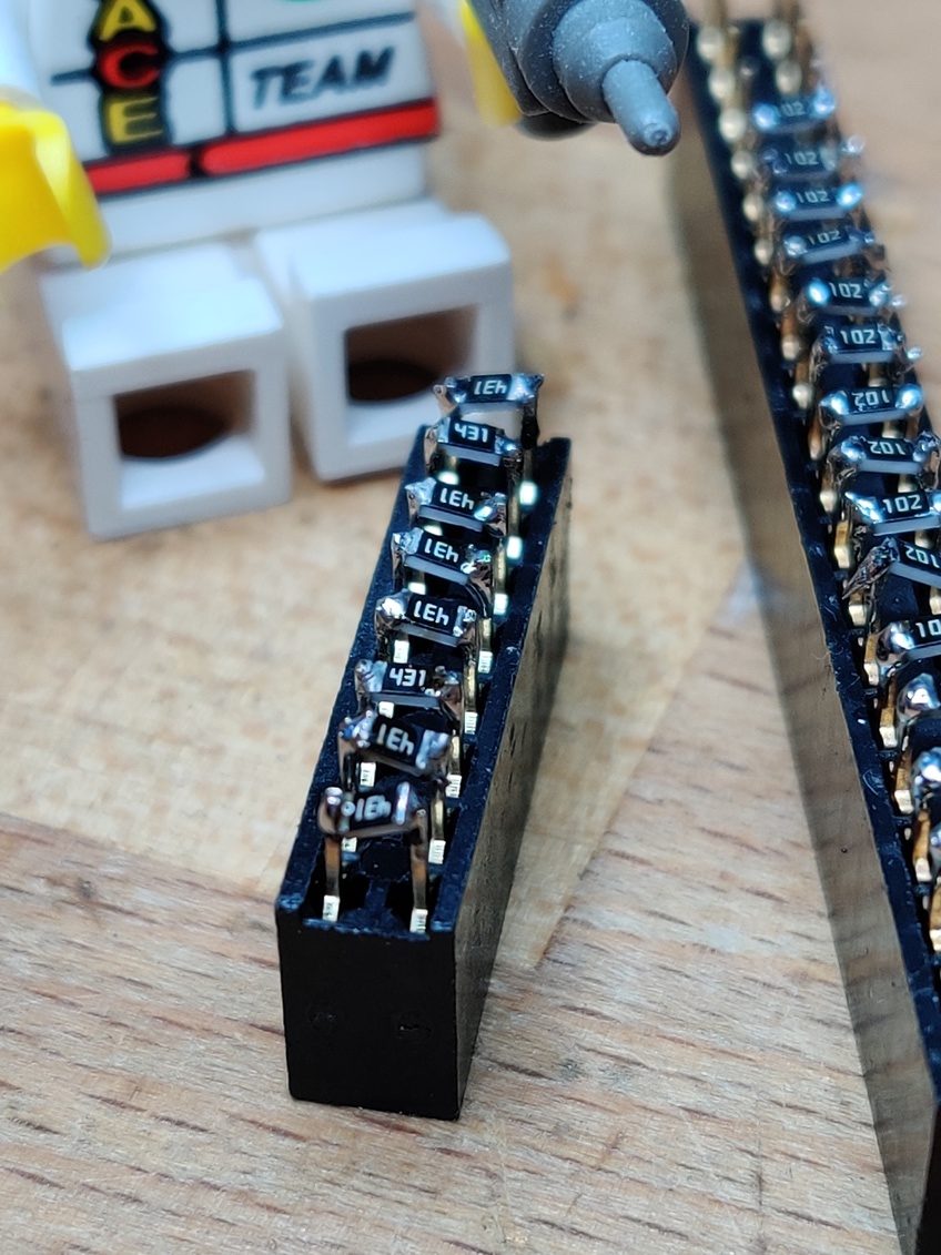
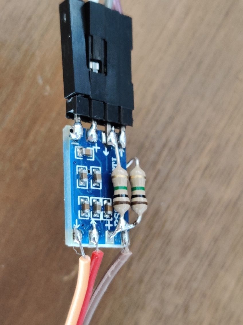
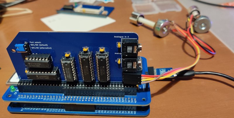
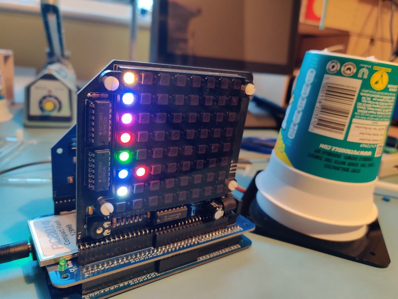
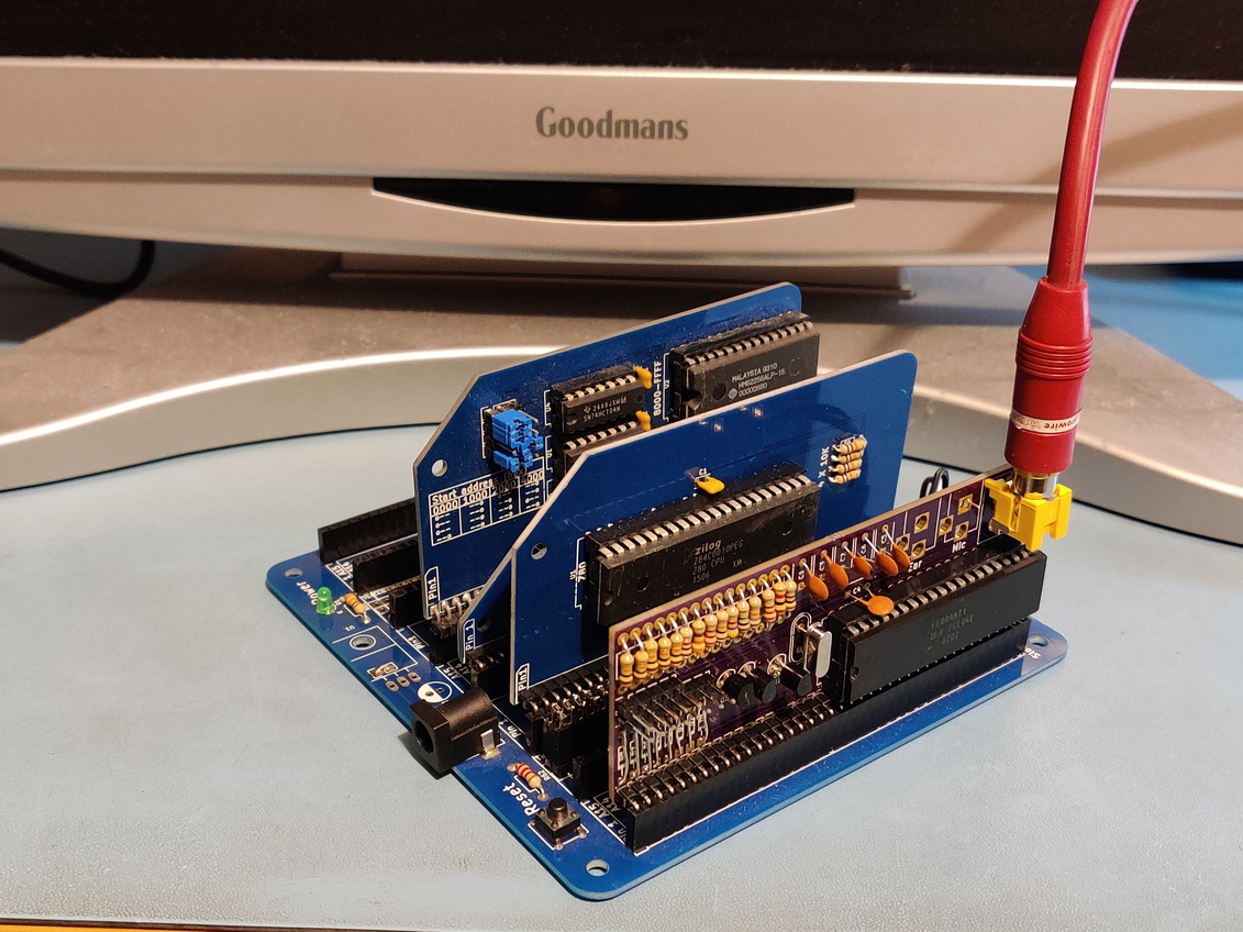
Rather than solder a load of resistors to the backplane though, I put header pins on there and then used sockets with badly soldered surface mount resistors on them. That way I could swap them out or replace them with jumpers if necessary.
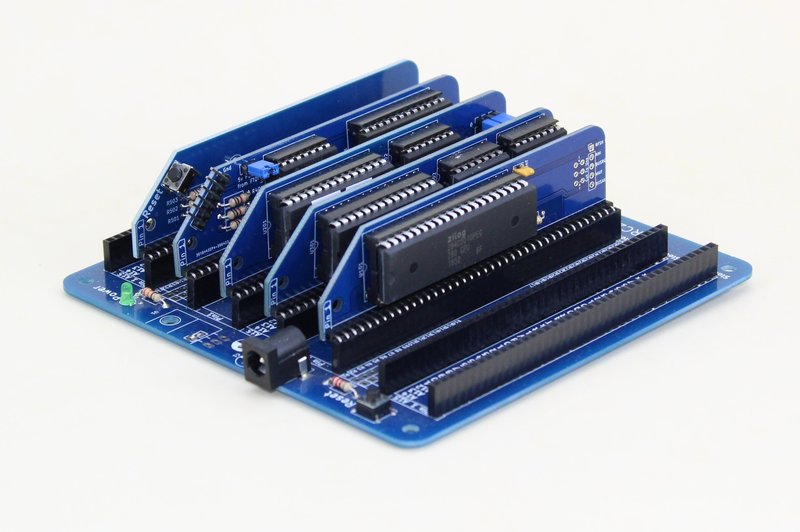
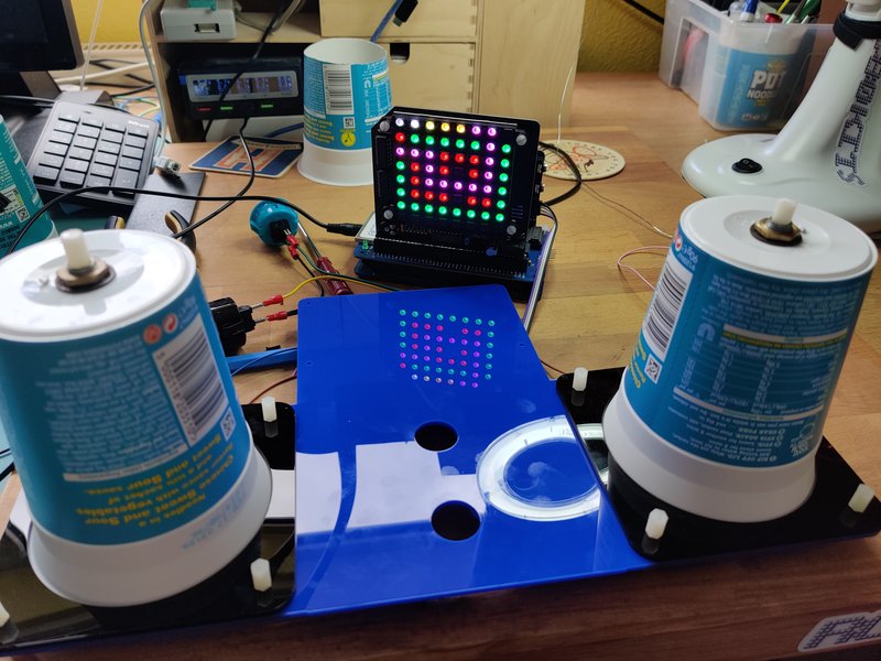
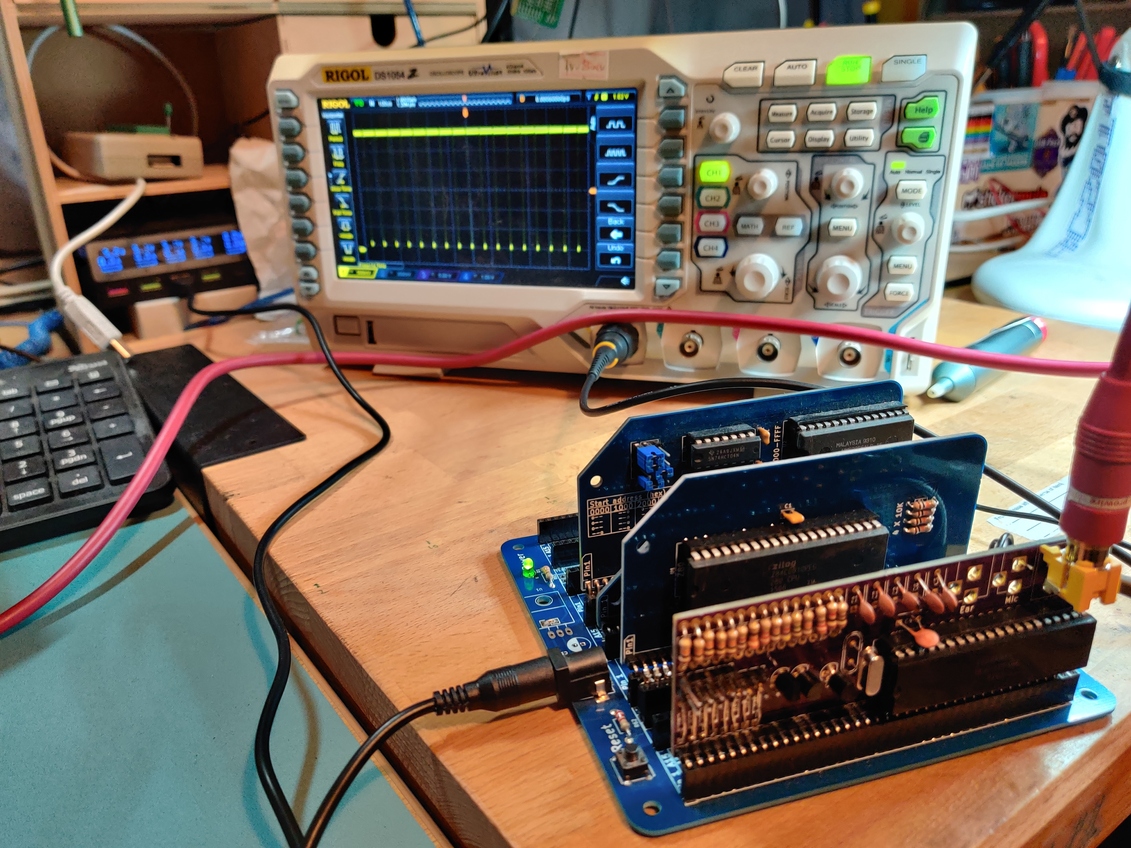
So, finally I had a completed module, a programmed ROM, backplane with resistors on it, and no more excuses for not powering it up.
So I did….
And…
Nothing.
Well, nothing with a combination of heat from the ULA. That is probably not good. I only powered it up for a few seconds, but it clearly got hotter than it should. So rather than risk doing any damage, I decided to go back to the schematics and look closely at everything on my module compared to the original ZX81 schematic.
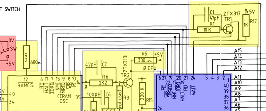
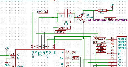
It didn’t take long before I found a discrepancy. The transistor at the top has the emitter connected to the NMI signal on the ZX81, but my module had it connected to the WR signal. I don’t know exactly what the effect of this would be, but I know it isn’t going to give the desired outcome!
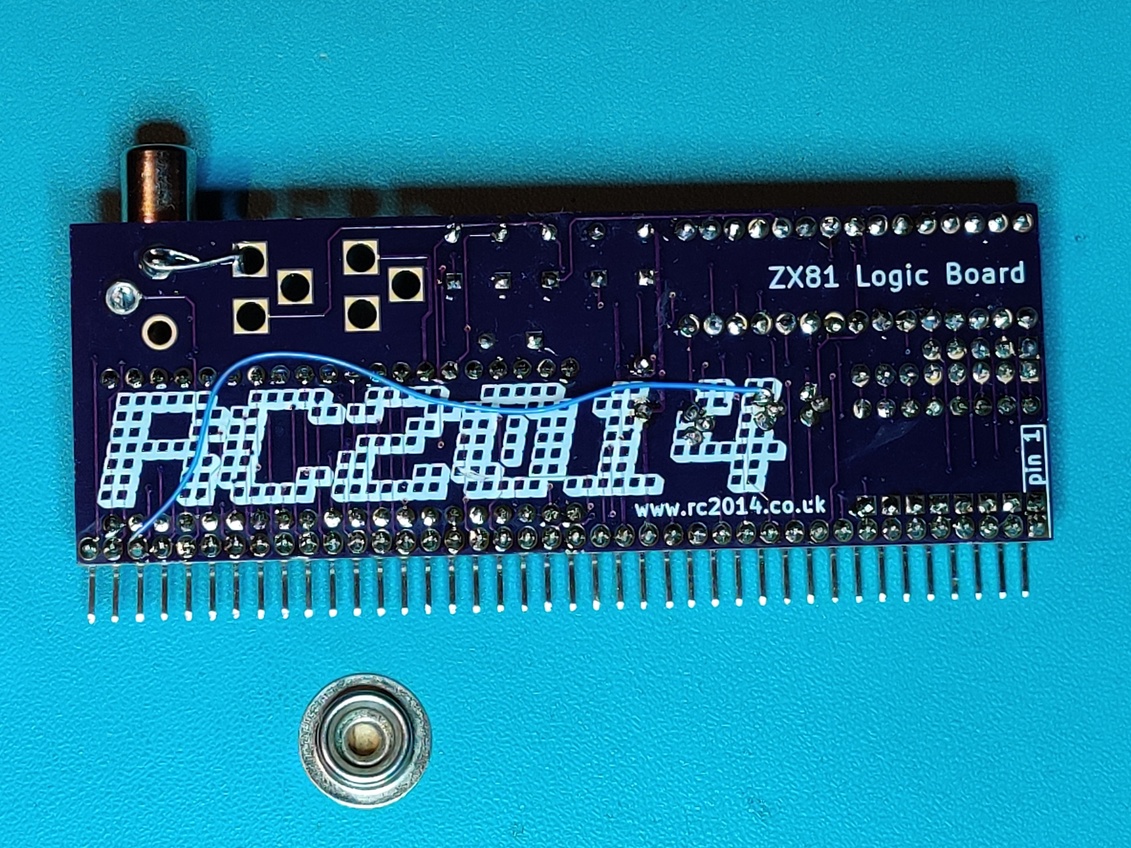
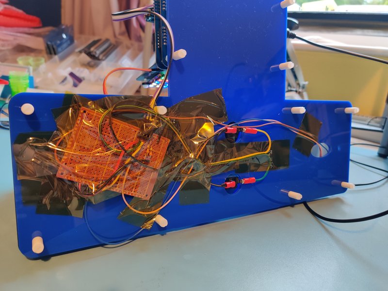
Luckily the fix isn’t too difficult. One track needs to be cut, and a wire needs to be added.
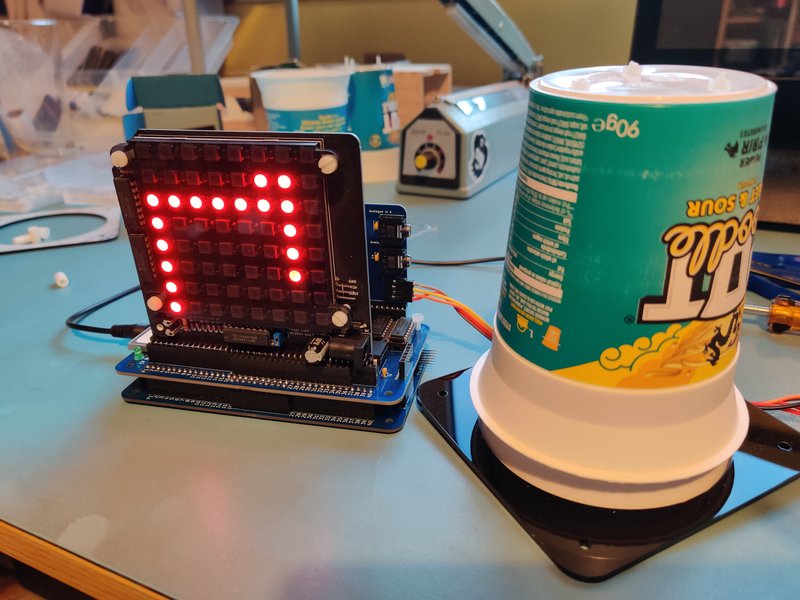
So, with that fixed, everything should power up just fine, right? Right? Sadly, no.
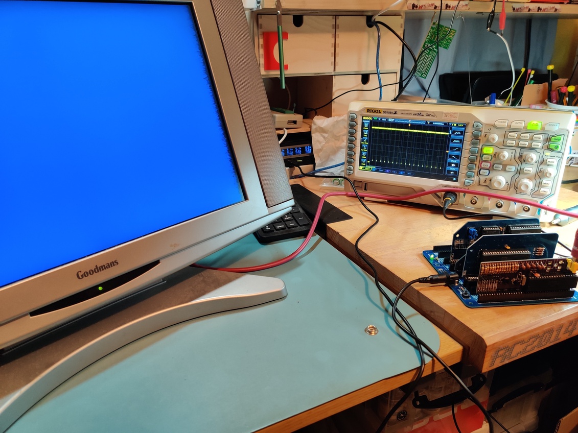
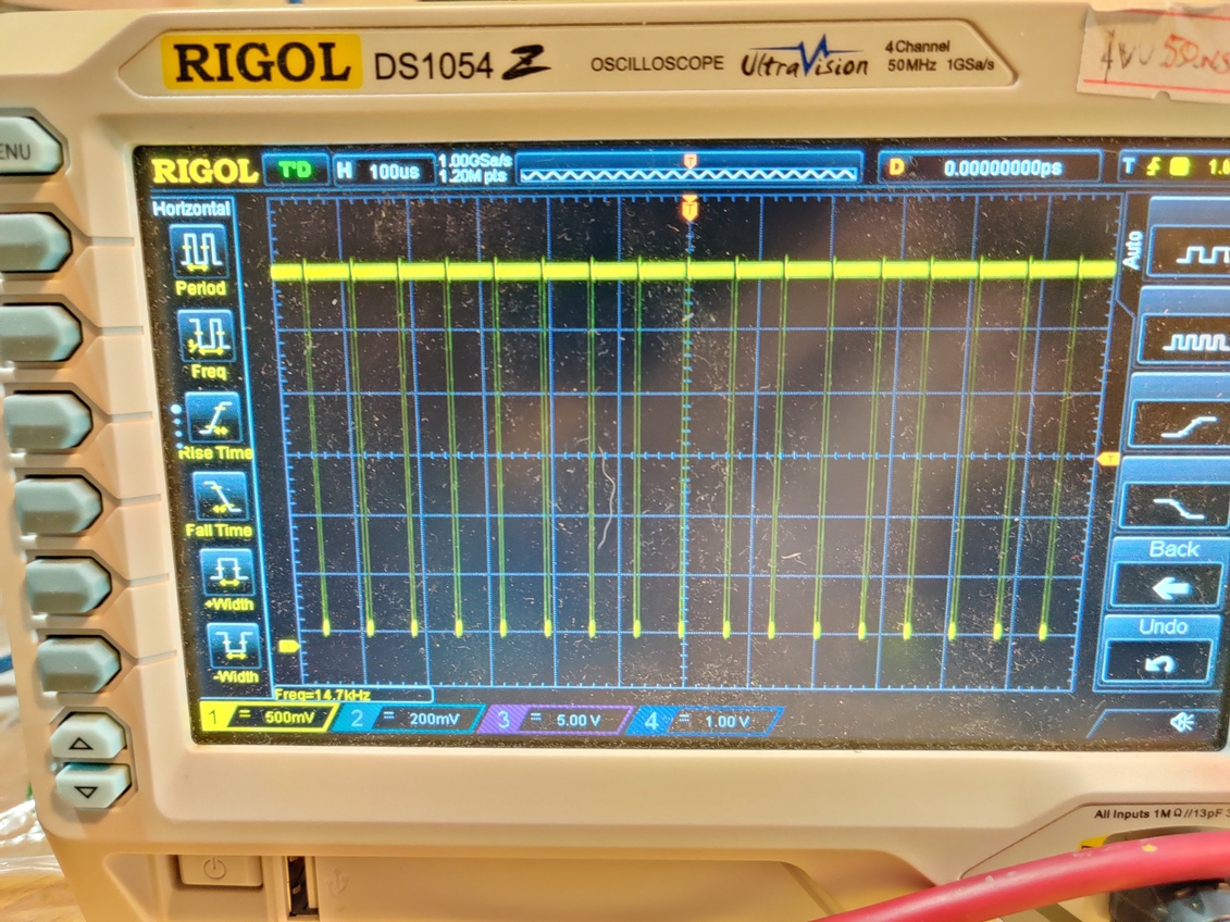
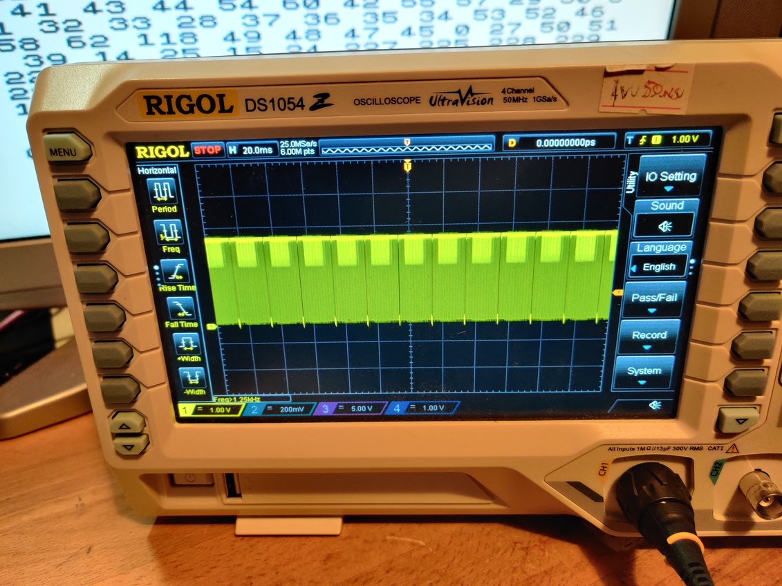
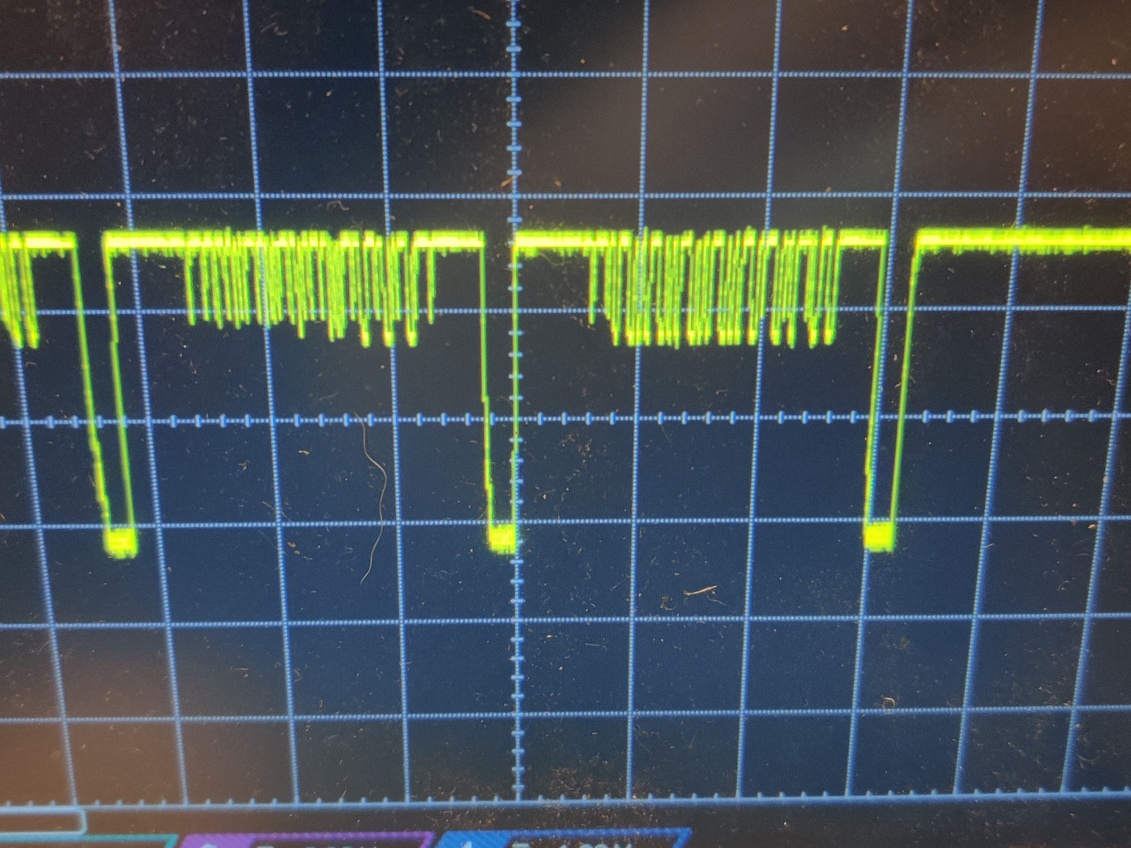
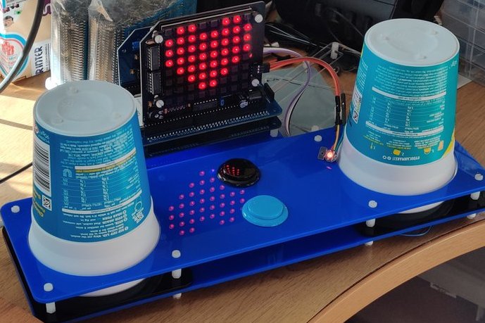
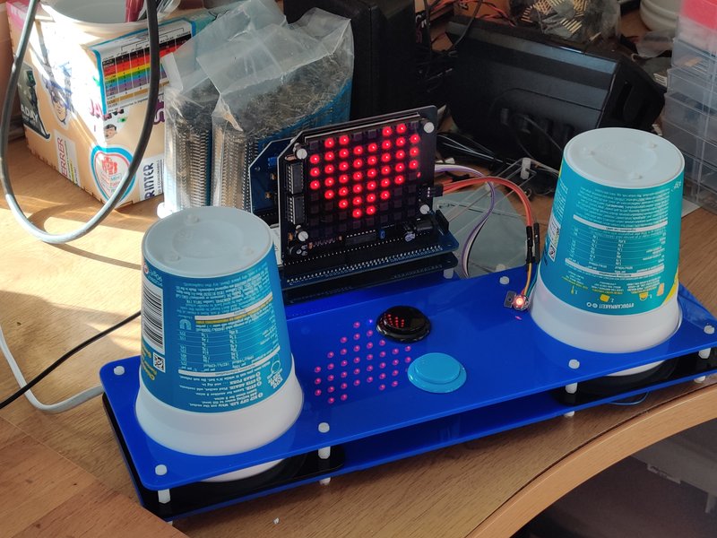
The ULA didn’t get hot, though. So that was definitely better. There was also a regular pulse on the composite output that looks a lot like a line sync signal. But there is nothing else.
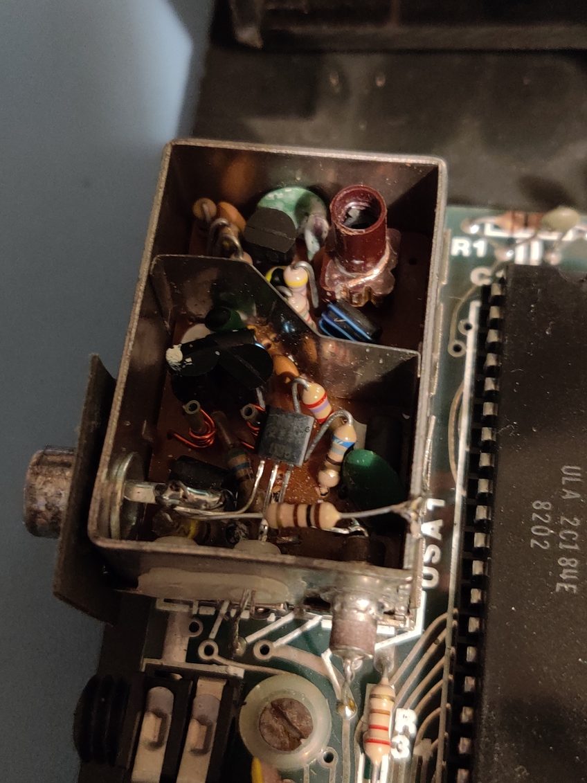
Time to look closer at what I did in 2016. Whilst there were very few components soldered on to the PCB back then, 2024-Me assumed that those were at least correct. Which turned out to be a mistake! The ZX81 uses a 6.5MHz crystal. However, I had soldered a 7.3MHz crystal on to the board. Why? I really have no idea. I also have no 6.5MHz crystals either. The closest I have is 6MHz.
As video signal is derived from the crystal, the value has to be pretty accurate. Without the right crystal this is never going to generate a white screen with a happy little K cursor in the bottom corner. However, a poke around the data and address lines makes it look to me like the rest of the computer isn’t running either. So even with a picture being generated, I doubt it would include a K cursor on it.
Schrödinger’s PCB has finally been observed, and it is currently not working :-(
Why? I do not know. There are several aspects that might be playing a part. So for Retro Challenge 2025 I will certainly need to address these
- 6.5MHz crystal needs to be obtained
- ULA needs to be checked. I don’t think the few seconds where it got hot killed it, but I cannot assume that it is totally undamaged.
- Limiting resistors need to be understood better
- Shadow copies of the ROM might need to be in the upper memory. I don’t think this is necessary, but it is a deviation from the original ZX81 design.
My decision in 2016 to base my module on a ZX81 because of the simplicity of a ULA might be flawed. In hindsight, the ZX80 might have been a much better place to start. There are a lot more chips in that design, but they are all regular 74 series logic, and each part of the circuit can be broken down and understood. That will demystify the Black Box of the ULA at least. I will leave it down to 2025-Me to decide if he wants to carry on with this module, or start afresh with the ZX80 schematic.