Wow! What an awesome month July has been. The whole Retro Challenge thing has been great, and despite moments of stress or despair, I have thoroughly enjoyed taking part and seeing what everyone else has been up to. Before I sum up my project, I should make a few honourable mentions.
Retro Challenge – A huge thanks to Mark and Wgoodf do a great job in hosting this twice a year. Keeping everyone updated via Twitter has worked really well. Cheers guys!
Grant Searle is responsible for the general Z80 design I used and also converted MS BASIC from the Nascom to run on this. Really, this project is a test of my understanding of Grants work and seeing how far I can take things.
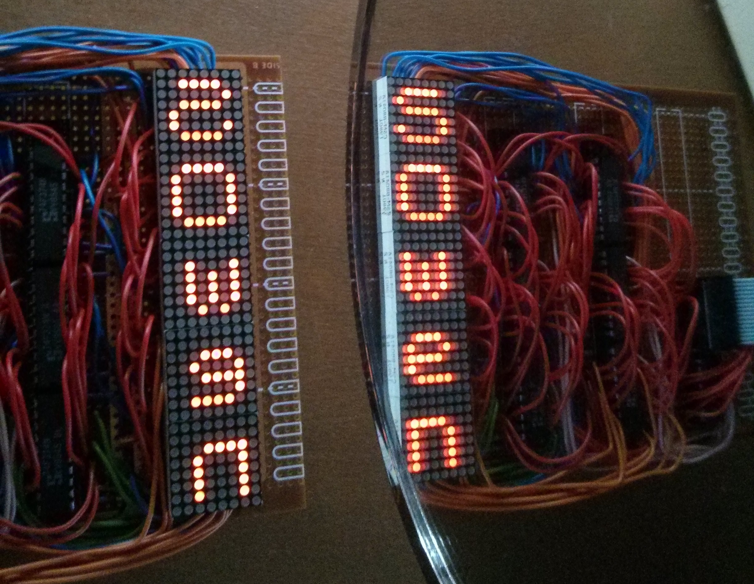
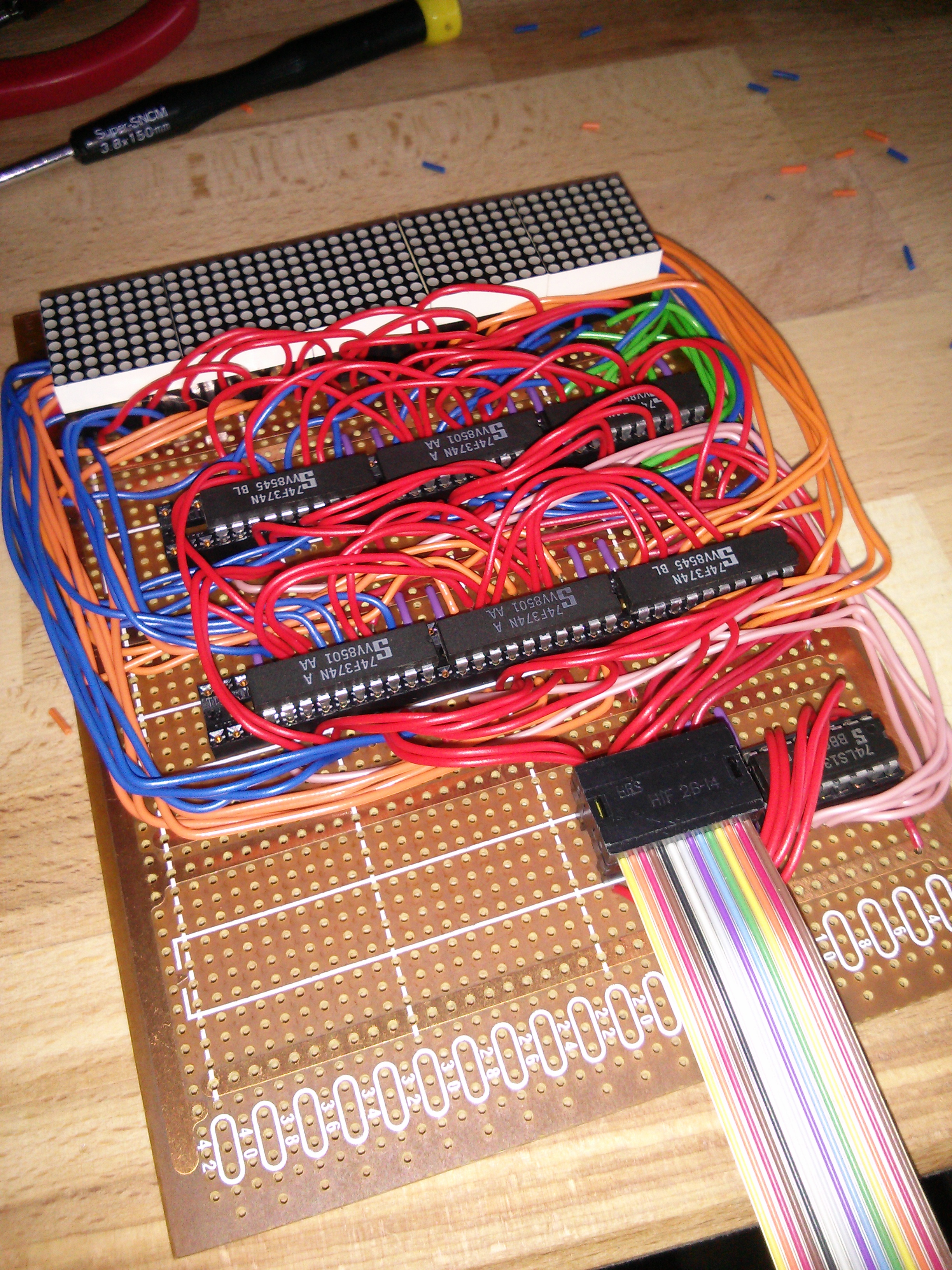
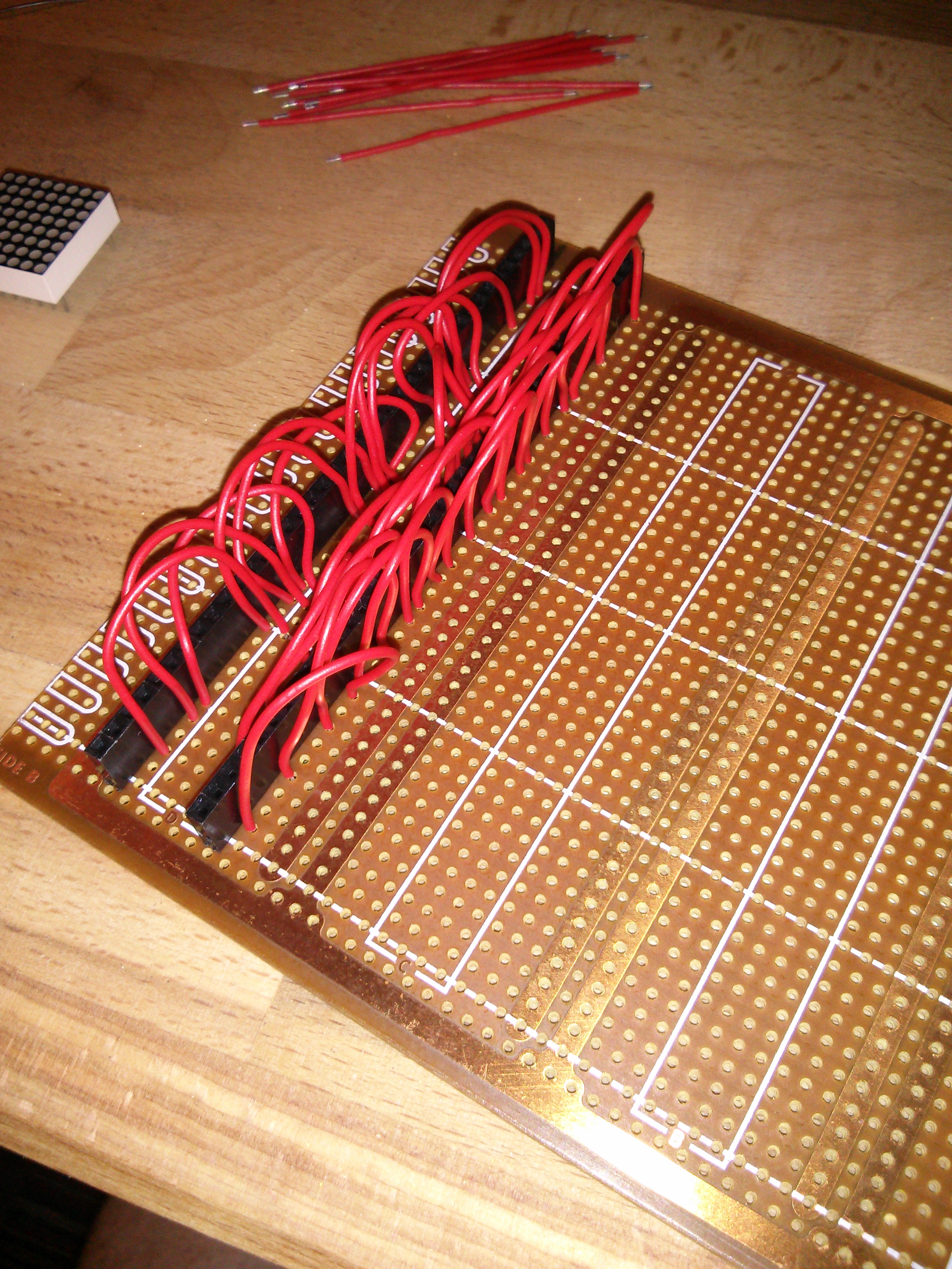
Nottingham Hackspace has an amazing “parts bin” that included the LEDs, Veroboard, case, some of the logic chips and the RAM I used.
OSHPark did a great job (for a very good price!) on the PCBs – even if the postal system did keep me on the edge of my seat for a bit!
Chris Gammell introductions to KiCad PCB design videos were critical in guiding me through the various stages of board design.
Rodney Zaks book Programming the Z80 has been like a bible for me. Combined with a few dozen other resources of Z80 info on line I’ve been able to at least get the basics assembly language programming.
CLRHome is a great online Z80 IDE that can compile assembly language in a variety of output formats including for the ZX Spectrum. I doubt I could have managed this in notepad!
All of the other Retro Challenge entrants deserve a mention too, but there’s a few that really caught my eye and taught me stuff about their particular approach to RC2014, such as Wgoodf – Turtles all the way down, Ians restoration of Northstar Horizon, Tezzas restoration and programming of Challenger 4P, John finishing work on Fahrfall

(more…)