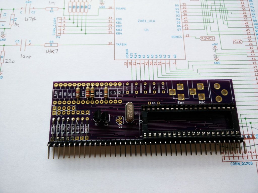
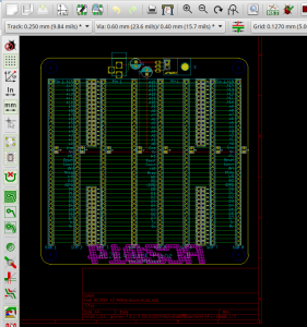
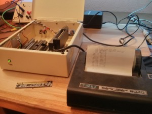
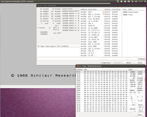
The schematic for the ZX81 Module I designed in2016 had been designed in a very old version of KiCad, and hadn’t survived all the upgrades too well. This resulted in every component being replaced by a question mark in a box. Luckily I had some photos of the schematic from previous Retro Challenge posts, as well as an expectation as to what should be resistors or capacitors or whatever.

Things now look much better, and actually make some kind of sense.

2016 Me didn’t consider the importance of putting component values on the schematic. Or the PCB. My module was based on the original ZX81 schematic though, so it was pretty much a case of matching up components and updating their values.
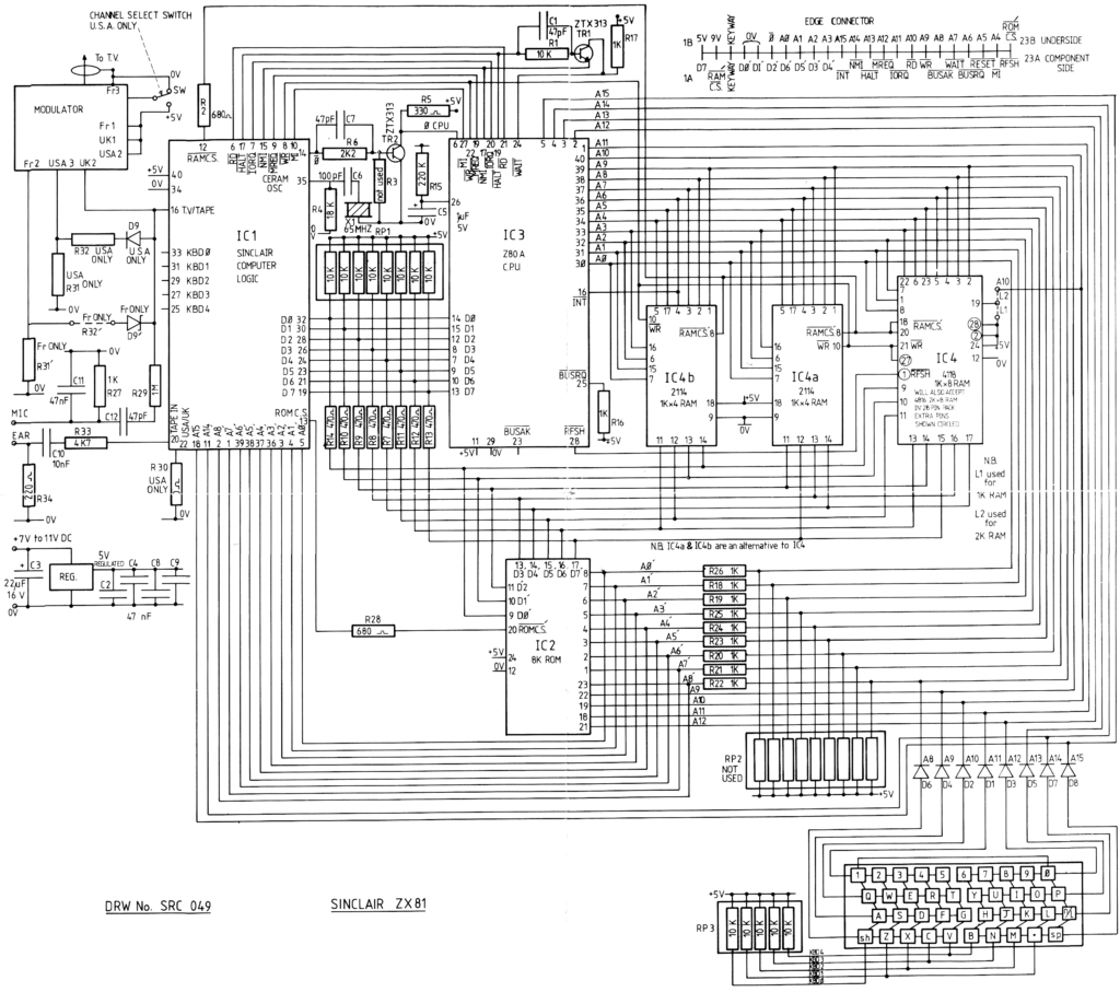
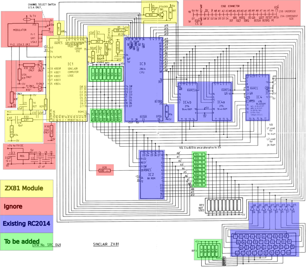
The observant amongst you will notice that the ZX81 schematic has a lot more stuff on it than my module. These changes can be categorised in three ways;

  • Components which the RC2014 already have, such as the Z80 CPU, ROM or RAM
  • Components which need to be added, but are not part of the module, such as the keyboard or data/address bus resistors
  • Components which will not need to be included, such as the TV modulator including the USA/French options, or power regulation.
In addition, I noticed my module design had some extra components that were not part of the ZX81 schematic.

More specifically, this is a transistor and resistor. This actually matches the composite mod that the donor machine had. So, well done 2016 me for thinking ahead and including this!
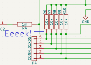
Something which is a bit more concerning though is the way that the keyboard lines all seem to be shorted against the TV Out netlist. I think this might be an artifact of the schematic rescue, as I am sure that 2016 Me would have noticed that. However, I still need to test the PCB in case this fault has made its way through to the board.

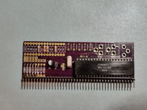
So, with a donor ULA, and all the component values, I have everything I need to finish the module. There are other important things that I need to do to the RC2014 though. Firstly, I need to burn a ROM.

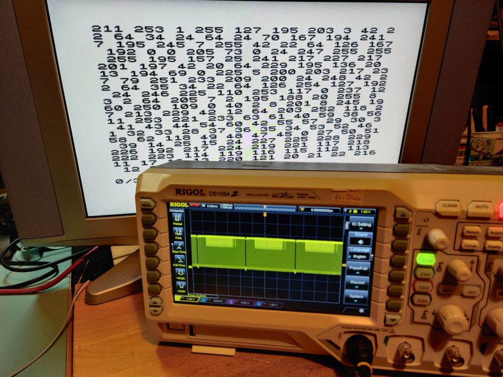
You may remember from a recent post that I did a partial ROM dump from the donor machine. This was a simple BASIC program

10 FOR F=1 TO 200
20 PRINT PEEK F;
30 NEXT F

I remember reading that the ROM chips used on old machines were almost, but not identical pin out to the 27C EPROM chips, and that it was a couple of data pins which were swapped over. Or something like that. So my worry was that, for example, D3 and D7 on every byte was swapped. So if I could compare the first 200 bytes or so then I would know if everything matched, or if the difference was consistent.
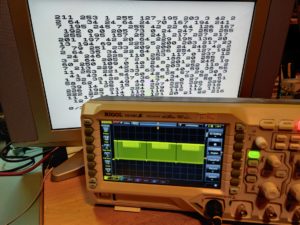
Luckily, everything matched with the ZX81.ROM file I have.
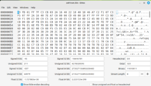
Although converting decimal to hex becomes less and less fun as you go. But at least I know that I should be able to just burn that image to a ROM and it *should* work.

The memory map on a ZX81 is a ZX81 is interesting. The ROM shows up in 4 locations, and the RAM is mirrored too. A13 is the only line used to decode if ROM or RAM is accessed. Therefor the memory map looks like this;

FFFF
      RAM (Shaddow)
E000
DFFF
      RAM (Shaddow)
C000
BFFF
      ROM (Shaddow)
A000
9FFF
      ROM (Shaddow)
8000
7FFF
      RAM
6000
5FFF
      RAM
4000
3FFF
      ROM (Shaddow)
2000
1FFF
      ROM
0000

As I understand it, Only the 8 ROM from 0x000 to 0x1FFF and the 16k RAM from 0x4000 to 0x7FFF actually matter. However, my plan is to burn two consecutive copies of the ROM and set the Pageable ROM Module to a 16k bank size. I will also use a 64k RAM Module with RAM starting at 0x4000. This will mean that the shaddow ROMs from 0x8000-0xBFFF will actually be RAM. I very much doubt that anything makes calls to that address range expecting it to be ROM, but as long as it isn’t critical to bootup, I can write a routing to fill that RAM with the ROM contents.

So, with all of that sorted out… I just need to solder some components, burn a ROM, and put it all together.

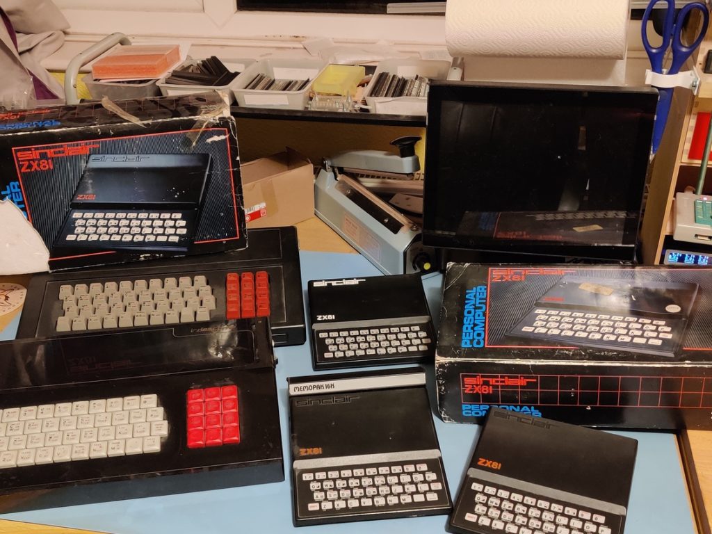
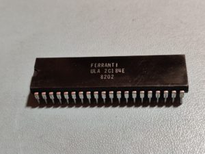
If you remember from my initial post at the start of the month, the first thing that I needed to do in order to make progress on the ZX81 Module was to find a donor for the ULA. Some things can’t be rushed though, so this has only just happened. Luckily I have several candidates to choose from.

I had some constraints though. Obviously the ULA had to come from a machine that worked. Ideally one that had undergone a composite mod. And preferably not the original one that my dads school friend bought back in the day and passed on to me a few years ago. (The ULA will only be borrowed to check that things work, but I would rather not risk damaging one that has sentimental value)

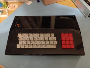
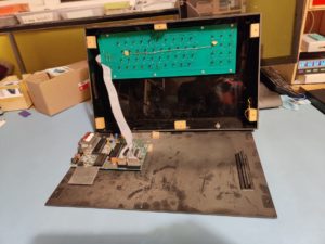
This one seemed to fit the bill. Apart from the fact that it is housed in a full size case with mechanical keyboard, there is nothing special about it. I think this may well have had various expansions or add-ons back in the day, but those are long gone now.

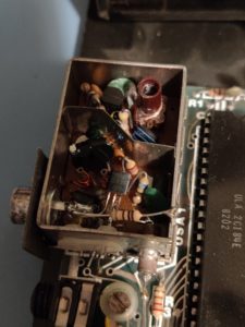
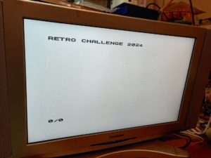
Luckily, it also has also been composite modded. In particular, this has been done via a transistor, rather than just sending the video signal out of the socket. This means that I can test that this works with my monitor before taking the ULA. I know that some modern monitors are fussy with ZX81 signals as there is no back-porch generated. Adding the circuitry to do that isn’t overly complex, but if I can keep things simple then all the better.

The TV image is actually really sharp, and certainly works with my monitor. So it looks like I have a donor chip!

Before removing it, however, there were a couple of checks that I wanted to make. Firstly, I have a file on my computer called ZX81.ROM which I think might be exactly what it sounds like. When opening it up in a hex editor, though, there is nothing readable in there at all. I would have expected to see something like the copyright message or the keywords listed. So I will take this opportunity to dump the first couple hundred bytes of the ROM to the screen so that I can compare it to the file I have.

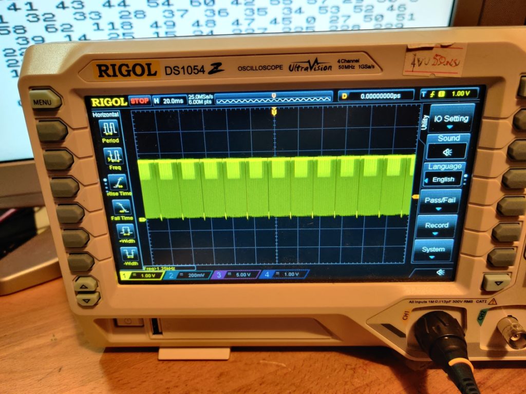
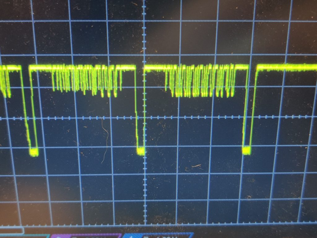
I also want to take a quick look at the output signal on a scope.

Everything looks good and just what I would expect from a video signal (without a back porch)

So, with no further ado, out comes the ULA, ready for its new mission in an RC2014

Next up, I need to finish the schematic so that I know what value components I need to populate the rest of this board…

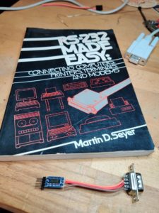
Following on from the failure to get the Portfolio talking directly to the RC2014, I decided to turn my attention to the Cambridge Z88. I already have a custom RS232 to TTL serial adapter for that, and the RC2014 is all set up ready for the Portfolio at 9600 baud, so this should be straightforward…

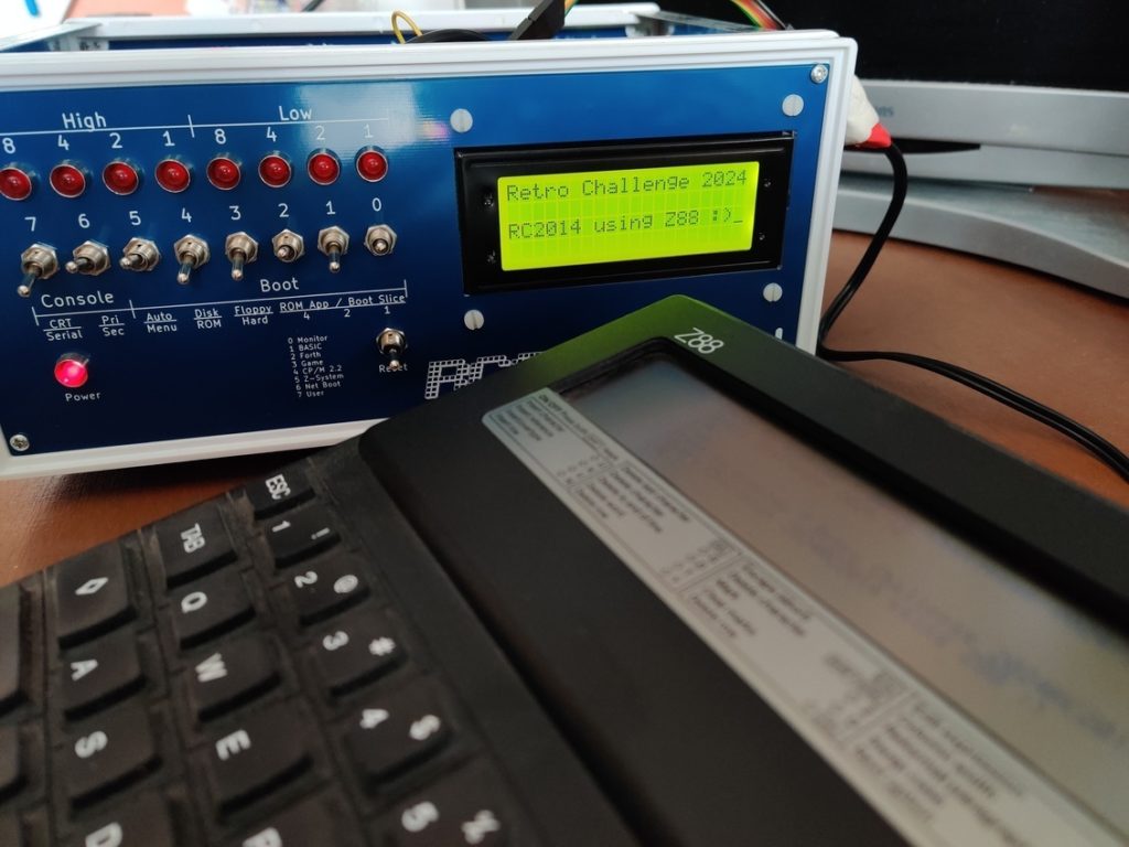
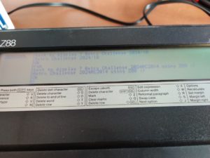
Well, would you believe it, it was a success! The Z88 is a fantastic machine, with some good built in programs. One of those is a terminal emulator, so it really was just a case of plugging the RS232 adapter in to the RC2014, with Port B set as the primary port set at 9600 baud.

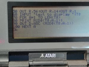
To test it properly, I typed in the test program for the LCD module https://rc2014.co.uk/modules/lcd-driver-module/ (The initial test failed, but after I plugged the LCD in correctly, everything worked fine).

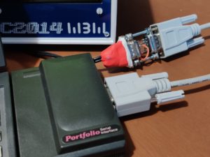
Buoyed on by the success there, I decided to turn my attention back to the Portfolio. Knowing that the Z88 RS232 to TTL serial adapter worked meant I didn’t have to burn my fingers again! The only issue was that the Z88 had an almost but not quite standard pinout on the DB9

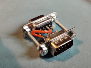
I blogged about the Z88 RS232 to TTL Serial adapter back in 2013 https://sowen.com/466/z88-to-ftdi-lead-via-max3232/ The important takeaway from this is that Gnd is on Pin7 on the Z88, although it is Pin5 on the Portfolio. It is also worth noting that Pin1 and Pin9 both carry 5v, and whilst these aren’t used in my adapter, they could break other things they are plugged in to. Pin2 and Pin3 are Tx adn Rx respectively on both the Z88 and Portfolio.

Time for a Frankenconnector to adapt them!

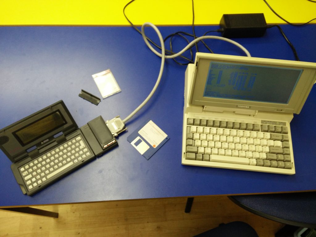
The other bit of unfinished business on the Portfolio was putting some terminal software on there. A copy of xterm2, as supplied on the Portfolio utility card was easy enough to find. In the past I had transferred programs to the Portfolio via the parallel adapter, however, I had recently bought an APF-01 memory card from https://apfram.com/ Whilst I had to use some propriety software on a Windows machine to copy the files on to it, it worked really well.

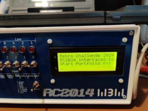
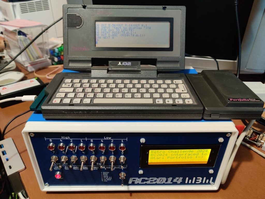
With everything connected up and Xterm2 started, the Portfolio and RC2014 were talking!

Again, I typed the LCD test program and sent a message to be displayed from the Portfolio to the RC2014

Although, of course, it was only as I type this blog post that I notice the Off-By-Ten error in that message! Ooops!

So, that is the Z88 and the Portfolio both ticked off of the list of computers to talk to the RC2014. Whilst the Portfolio wasn’t a complete failure before, I am really glad I revisited this and got a more satisfying result. And it has reminded me just how good both of those two machines are. I really should use them more.

Retro Challenge 2024/10 – Intro Post

It has been a while since I entered Retro Challenge, but I think I remember what to do. It goes something along the lines of stating at the start of the month by saying that you are going to design a ZX81 module for the RC2014, and then at the end of the month report back in with minimal progress. Looking back, I seem pretty good at that. Retro Challenge 2016/1 started off like this and ended like this. Then later for Retro Challenge 2016/10 it looked like this.

I hope you will excuse me for using the same image I finished on 8 years ago, but, honestly nothing has changed. The ZX81 module is still in this state.

So, before we get to far ahead of ourselves, lets take a look at how we got to this point. My original goal was to recreate either a ZX Spectrum, ZX81, ZX80 or Jupiter Ace module for the RC2014. They are all fairly similar architecture, although the Jupiter Ace has weird dual port memory RAM. They all have a Z80 CPU, some ROM, some RAM and a clock, the same(ish) as theRC2014, so those parts of the schematic can all be ticked off. The ZX80 does everything else with conventional 74 series logic. The ZX81 is almost identical, except that 74 series logic is all smooshed in to a ULA. The Spectrum is similar except the ULA does more stuff (which can also be done with 74 series logic).

I ended up choosing the ZX81 as a good place to start because it is pretty much just a ULA chip with a little bit of support circuitry. The ULA is no longer manufactured, which will mean taking one from a working ZX81 to get this up and running. There are, however, modern FPGA replacements available, so I might well end up getting one of those to swap in at some point. So in January 2016 I translated the relevant parts of the ZX81 schematic in to KiCad and designed a module around that. I got some boards made, but that was as far as things got. Then later that year I soldered in 9 components.

To get started this year I need to do two things. Firstly, familiarise myself with the ZX81 circuit and the one I designed 8 years ago. I seem to remember being fairly confident it would work, but at this stage I have Schrodingers PCB. It both works and does not work simultaneously, needing a test to clarify the actual state. The second thing is that I need to check my stock of ZX81 and select a donor one that the ULA can be borrowed from. I probably want to make note of some of the pin voltages or signal traces before taking it out so I can check those when it is in the module.

There is a chance that I will end up waiting for parts, so the secondary part of my Retro Challenge challenge is to talk to my RC2014 with as many of my retro computers as possible. This may include but not be limited to;

  • Atari Portfolio
  • Cambridge Z88
  • Psion Organiser II
  • Psion Organiser 3a
  • Sinclair Spectrum (with Interface I)
  • Sinclair Spectrum 128
  • Sinclair Spectrum +2 or +3
  • Sinclair QL
  • Amstrad PPC640
  • Toshiba T1200

I think this will be limited to serial communication, and luckily I have a few MAX232 chips and boards here. I expect it will mainly be using the device as a serial terminal for the RC2014, but it would be nice to maybe send a Spectrum loading screen from the RC2014 to the Spectrum. It might sound trivial, but understanding how the serial ports work on those devices, and finding/writing software to use them could be the challenging part.

Retro Challenge 2016 – My Dog Ate My Homework

So, all the way back in deepest darkest December, I announced I would enter the Retro Challenge 2016 competition that ran throughout January.  Those of you that followed by blog or Twitter account when I did this in 2014 will know that I blogged and Tweeted relentlessly for the whole month, but, this time around, almost nothing.  Obviously, I’m keeping some secret about an amazing breakthrough or something, right?  Well, truth is, I’ve done almost nothing.

Things started well, and on 1st January, I designed a new backplane for the RC2014.  Although I hadn’t studied the circuit diagrams for the ZX81, Jupiter Ace or ZX Spectrum yet, I knew that there were resistiors between the Z80 CPU and other devices.  The stripboard backplane I’d been using had served me well, but it was time to progress to a better solution, and one that could be adapted better to my needs.  Knowing that PCB delivery times could be against me, I thought it best to crack on and get this  ordered.

Screenshot from 2016-01-31 16:01:00

The basic circuit is very very simple – however, I wanted to get this just right, not only for Retro Challenge 2016, but for other possible RC2014 uses.  Essentially, there are 8 40 way connectors that are linked straight through – however, the data lines and address lines for the leftmost 2 connectors and rightmost 2 connectors are separated by a pair of pads.  These can either be shorted together for up to 8 commoned connectors, or have resistors soldered across them.  I also added a power connector and the option of either running 5v directly in to the board, or regulating a higher voltage down via a LM7805.

(more…)

Retro Challenge January 2016 – Preamble

So, you may well remember that I entered Retro Challenge 18 months ago, and what a fun crazy busy time that was!  Well, the January Retro Challenge competition is about to kick off in just over 2 weeks.

If you’re not familiar with Retro Challenge, shame on you!  But you can de-shame yourself by heading over to http://www.retrochallenge.org/ and seeing what it’s all about.  Essentially, it’s a month long bi-annual competition where the entrants set themselves a goal based around old school computing and blog, tweet and share their experiences.  The goals are pretty loose, as long as they are based on something from last centuary (modern emulators of old kit is fine).

The challenge I set myself was to take a breadboard based Z80 computer and bring it to life in modular PCB form in such a way that I could spell out my name on.  Have a look back through my blog to see how I did.  Spoiler —->

IMG_20140730_205950

(more…)

RC2014 with ZX Printer interface

My original plan had never been to design and build my own computer.  I had, however, planned to build a clone of the Sinclair ZX80, which has been on my bucket list of things to own for year, and which I had found plans for online.  Whilst collecting the parts and reading up on simple Z80 computers I got kind of sidetracked and ended up with the RC2014.

The print out shown was what was left from the last time this was connected to a ZX Spectrum!

The heart of the RC2014 is a Zilog Z80 CPU, which is the same one that Sinclair used in the ZX80, ZX81, ZX Spectrum and Z88.  If the ZX81 and ZX Spectrum can run a ZX Printer, then surely it follows that the RC2014 will be able to too?

(more…)

Retro Challenge – New IDEa

just a quick update about my Z80 development environment.

If you look down a couple of blogs, you’ll see that I found an online Z80 emulator and I’d written a couple of bits that executed in it, so I was going to do my Z80 learning and development on that.  However, there were two issues.  The first being that it didn’t run on Chrome on my Linux PC at home (but did on Chrome on Windows at work).  The second issue is that it isn’t a Z80 emulator, it’s a 8080 emulator.  I didn’t think this would be a problem as they pretty much run the same instruction set, although the 8080 has a sub-set of the Z80 (well, technically, as the 8080 came first, the Z80 has an expanded instruction set), and I quite quickly came across an instruction that wasn’t supported.  Bugger!  That’s messed up that plan.

Then I remembered I have Fuse which is a ZX Spectrum emulator running on my Linux PC.  There are oodles of menus and options which I’ve never looked at, but thought it worth a poke (no pun intended) about with.

Screenshot from 2014-07-16 22:31:09 (more…)

Retro Challenge – Font Selection

So, if I’m going to write my name on a bunch of 8×8 LED matrix displays, I have a couple of options; Write my name on grid paper, colour in the squares, convert it to binary and transpose it to hexadecimal.  Or… I could use a font that’s already out there.  Like the one that Sinclair used in the ZX Spectrum.

I’ve already got a copy of the Spectrum ROM, and, handily enough, all the characters are right at the very last part of the ROM address space (from 0x3D00 to 03FF), in consecutive blocks of 8 bytes.

I can see this coming in handy later! (more…)