With over 24 hours to go before the end of July deadline the final piece of the puzzle fell in to place!
But, first, a quick catchup from the last blog post;
With over 24 hours to go before the end of July deadline the final piece of the puzzle fell in to place!
But, first, a quick catchup from the last blog post;
Despite a late start today, things have gone well so I actually feel like I’m ahead of the game right now. Certainly not finished, but with most of the major hurdles now behind me, the only thing left is writing a bit of Z80 assembler code. And even that is starting to look manageable.
(more…)
So, exactly 3 weeks after they were ordered, the PCBs from OSHPark arrived today. It’s just as well, as I was running low on things to do without them, and with just 6 days left of the Retro Challenge I would have struggled to finish in time.

Well, that’s my weekend planned out for me now! (more…)
Just a little update as I’ve only done a little bit of work on the Z80 this evening;

The LED matrix board now plugs in to my Z80 backplane!
Sorry I’ve not made any updates for a couple of days, but there’s not been much of significance to report of late. Until today, that is. Although, as far as the PCBs I’m waiting for are concerned, the only news to report there is that there is no news to report. I will report tomorrow if there is news to report on this or not.
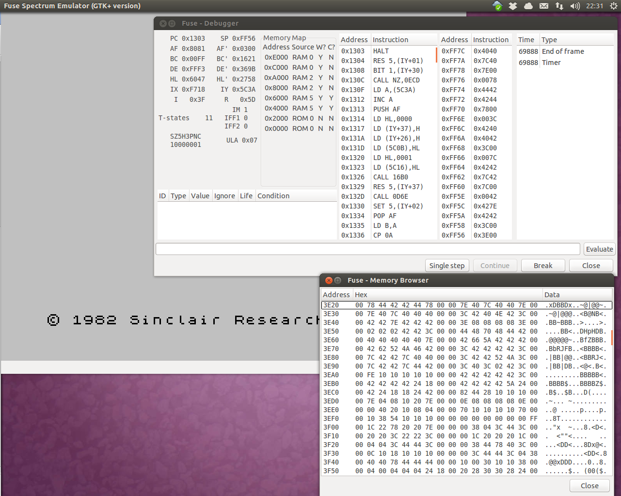
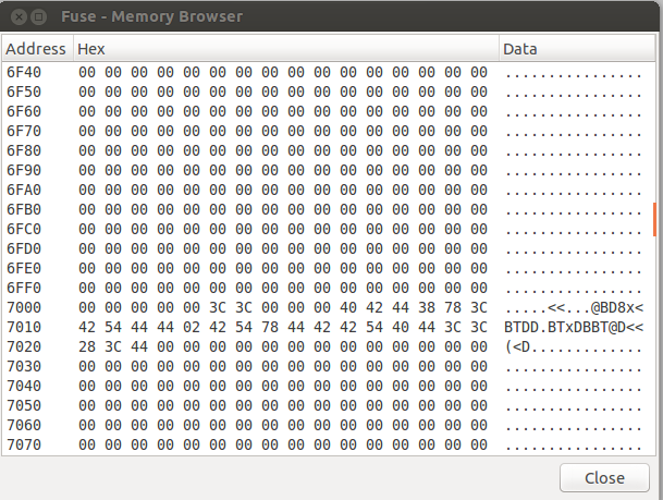
I have, however, been plodding away at teaching myself Z80 assembler language. And with some progress too! I’ve managed to pass the first major milestone with the code I’m writing to display text on the LED matrix displays! It basically, looks at some text stored in a memory location, then looks up each character in turn on the ASCII character map that I lifted from a ZX Spectrum ROM, and puts each line in every 5th byte in a different location. This new location is essentially a 40 byte screen map for the matrix
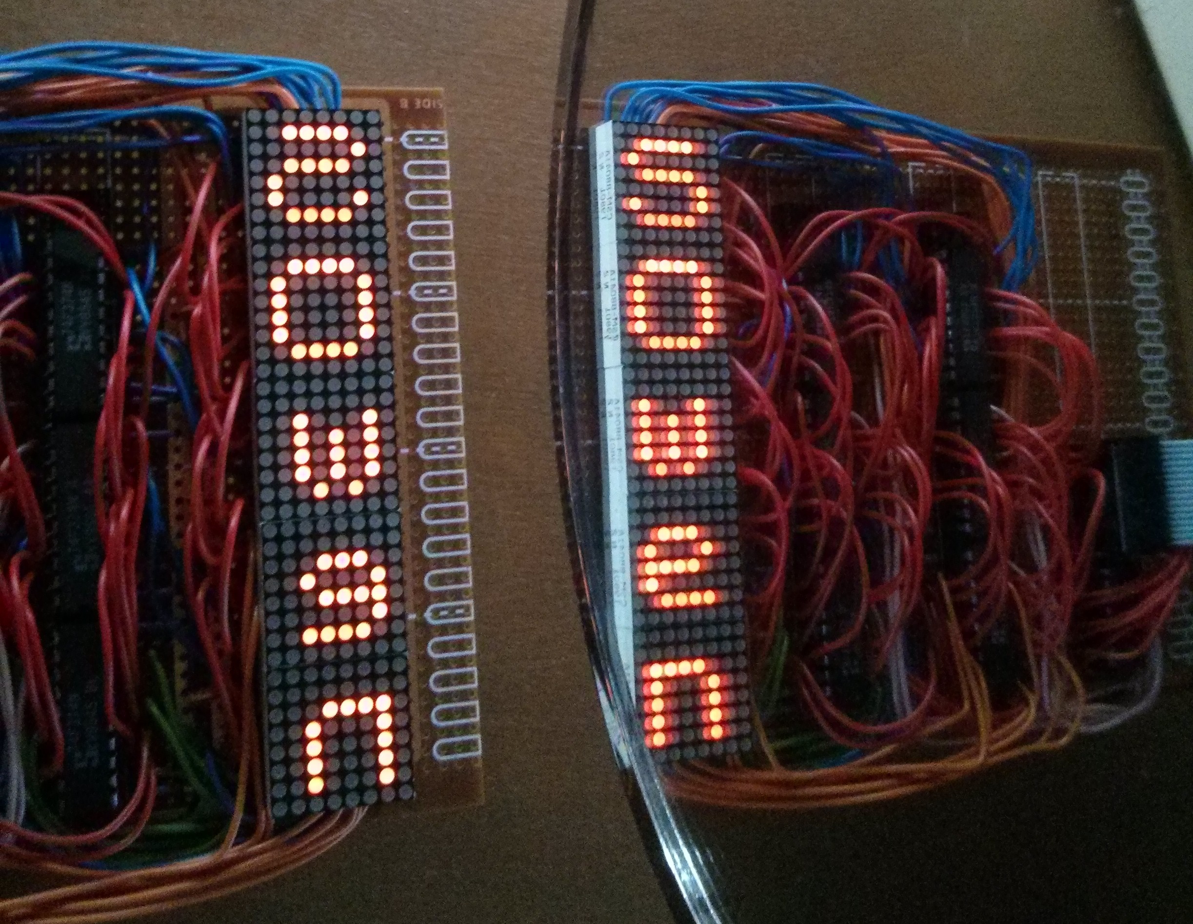
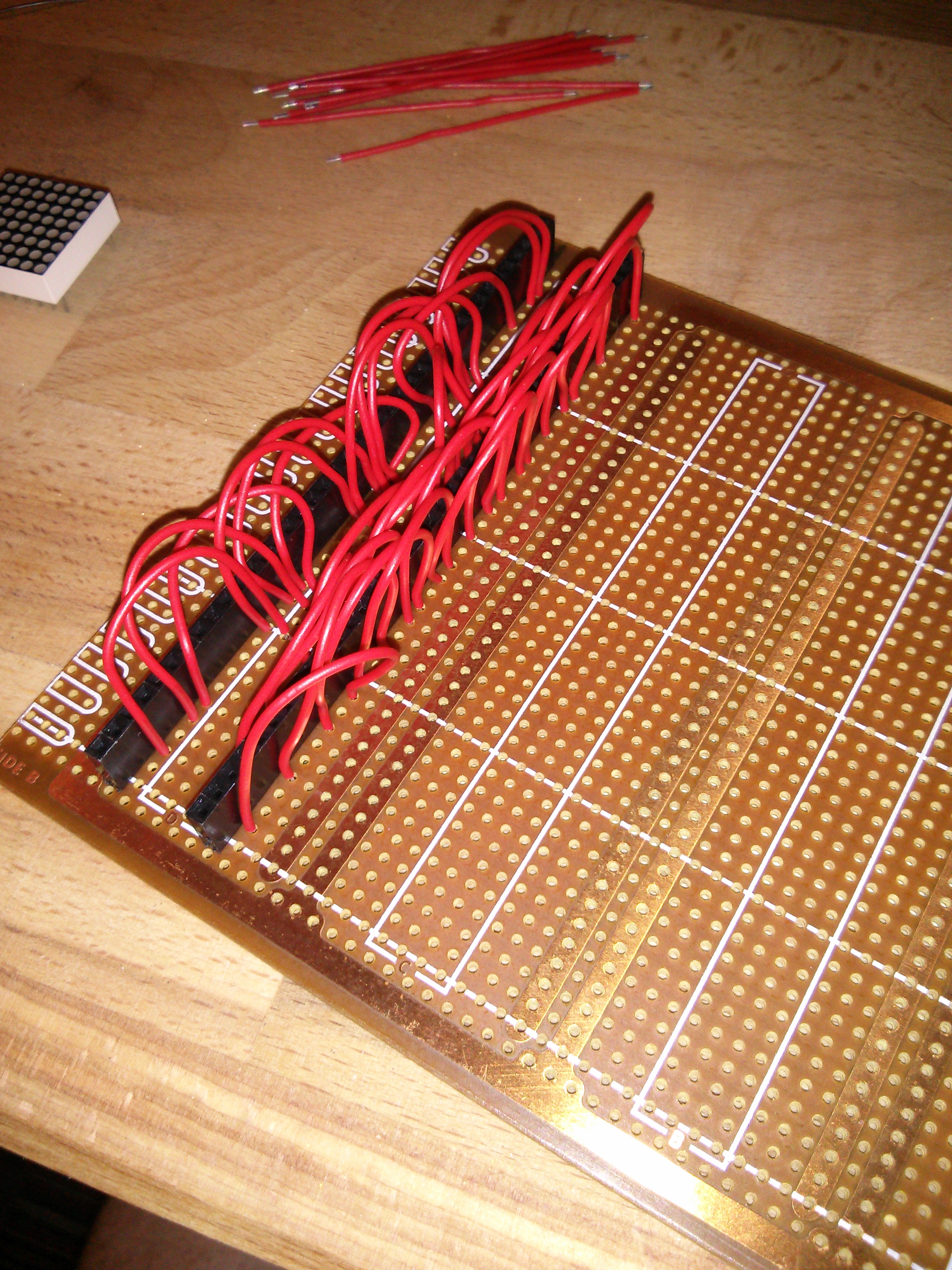
The 5 matrix board has now been finished. And no one could be more relieved than me. There’s a LOT of soldering going on in there!
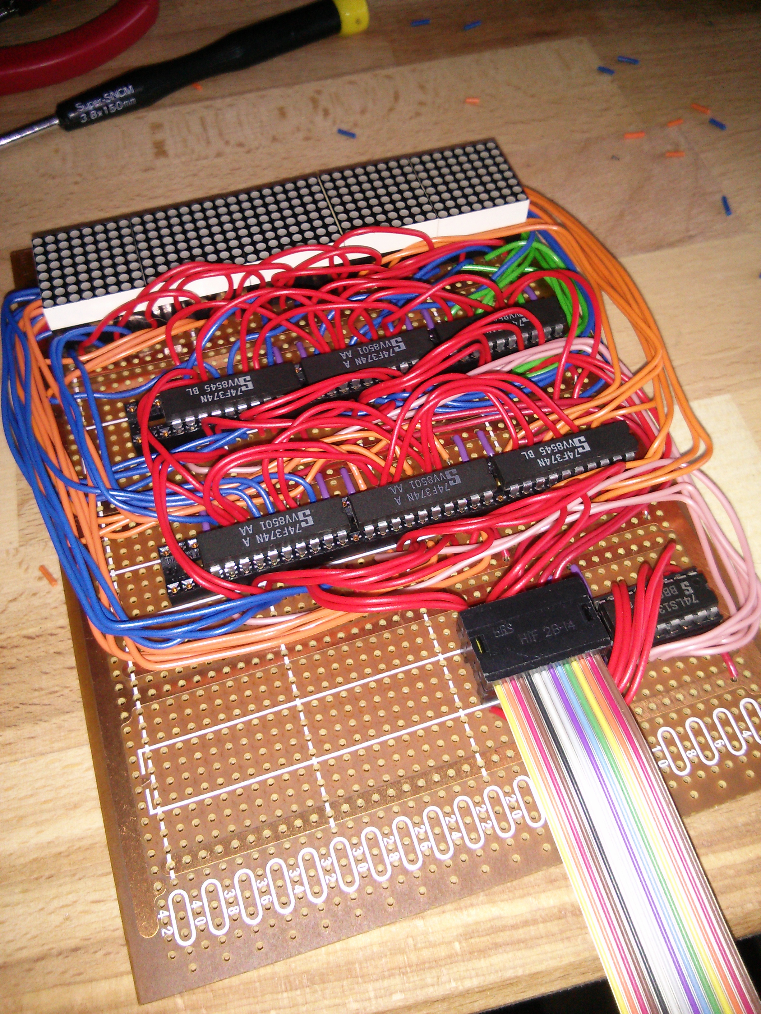
The mounting of the LED matrix has probably caused me the biggest turmoil so far on the Retro Challenge. First, I was going to design a custom PCB for them, but I missed the window of opportunity to get it manufactured at a reasonable price. So, for simplicity, I decided to use breadboard until I realised this wasn’t simple with that amount of wires. So, I went back to PCB design preparing to take the financial hit. However, it proved impossible to get the tracks to fit, so this idea went in the bin again. Back to breadboard, I bought a load of jumper cables, and started expanding on what I started earlier. For the driver chips it was ok. For the matrices themselves though, I came across a show stopper; The width of it is so wide that in the breadboard there are 2 free tie points on one side but just 1 on the other. Getting a data bus down all of them was not going to be possible :-(
So, I had a rummage through some vintage Veroboard and found a Euro-card sized board with chip layout tracks. It would only fit 5 modules side by side, but I was prepared to make that sacrifice. I also had some 40 pin female sockets, so that made life even easier!
just a quick update about my Z80 development environment.
If you look down a couple of blogs, you’ll see that I found an online Z80 emulator and I’d written a couple of bits that executed in it, so I was going to do my Z80 learning and development on that. However, there were two issues. The first being that it didn’t run on Chrome on my Linux PC at home (but did on Chrome on Windows at work). The second issue is that it isn’t a Z80 emulator, it’s a 8080 emulator. I didn’t think this would be a problem as they pretty much run the same instruction set, although the 8080 has a sub-set of the Z80 (well, technically, as the 8080 came first, the Z80 has an expanded instruction set), and I quite quickly came across an instruction that wasn’t supported. Bugger! That’s messed up that plan.
Then I remembered I have Fuse which is a ZX Spectrum emulator running on my Linux PC. There are oodles of menus and options which I’ve never looked at, but thought it worth a poke (no pun intended) about with.
We’re at the halfway mark of the Retro Challenge, and there’s a slight lull in activity, so this seems like a good chance to catch up on what’s been done so far, and what’s still to come.
Firstly, a quick review of the challenge I set myself; write my name in LED lights. These must, however, be controlled by a Z80 computer, which I’ve got to design and build myself, and written in assembly language which I need to learn.
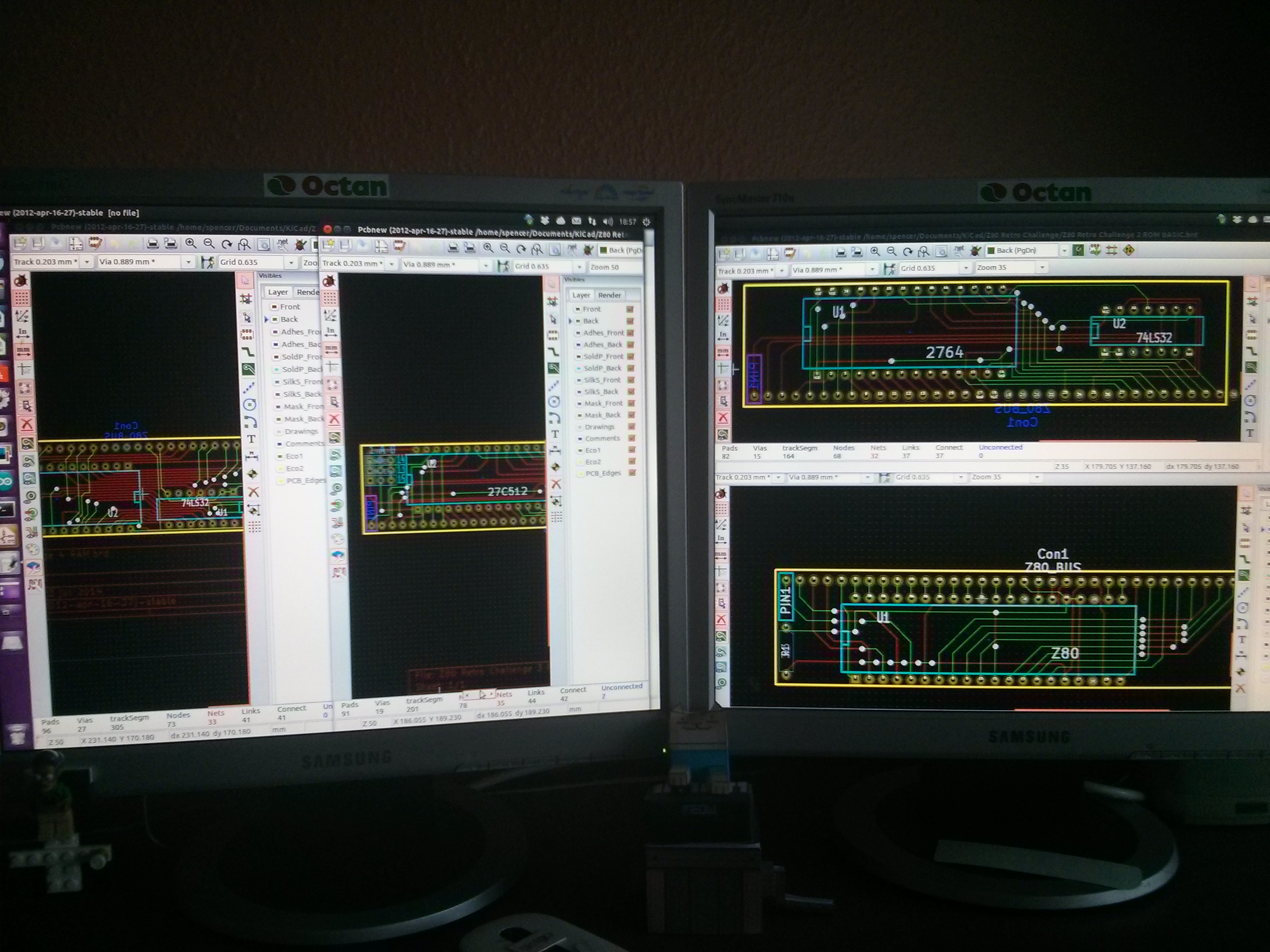
Well, the start of the challenge saw me dive headlong in to KiCad, learning some of the intricacies of printed circuit board layout. I’d used KiCad for a couple of little projects before, but certainly wouldn’t have described myself as competent. I’m still not a master of it, but I’m a lot more familiar with it than I was.
I split my breadboard based Z80 down in to several modules, each of which will plug in to a Veroboard backplane. 6 of these have been designed and sent off for manufacture which will give me a basic Z80 computer that I can use via a terminal emulator. The boards are;
I knew there would be some stumbling blocks with this Retro Challenge, but, hey, it wouldn’t be a challenge if everything was just nice and simple. However, I seem to be beset by little stupid technical issues that aren’t necessarily retro in nature.
However, the fact that you’re reading this does at least mean that my blog is working again! I ran some updates last week, and it caused some issues with a plugin meaning I had no way of adding, editing or modifying any posts. I’ve now got that tracked down to the Poll plugin and disabled it. So, yay, I’m back!
So, part of this challenge is to use LEDs, and the little 8×8 matrix modules I found seem ideal. I had initially intended to design a PCB to mount a bunch of these on, but due to time constraints, it was looking very unlikely I’d get them designed, ordered, manufactured and delivered by the end of the month, let alone time for testing. So I decided to go Old Skool, and do this part on a breadboard. Well, 2 breadboards, as they each need a driver chip. Although, it’s actually 3 breadboards, as 2 aren’t quite big enough. Not to mention the other breadboard with the supporting circuitry on. I made a start on this last night;