Retro Challenge 2017/10 – Live Zork Streaming Soon

Firstly, apologies that not much has happened recently.  I’ve been under the weather for the last few days, so only made minimal progress.  However, feeling a bit better, so Tonight I will try streaming Zork!

I am planning to go live at 7PM UK time tonight for around an hour (If you’re not in the UK, see this countdown timer).  If you missed it, I’m sorry – but I hope to have a transcript up soon, and will probably do it again shortly.

There will be a tweet beforehand with links to connect to, so if you don’t follow @ZXSpectROM on Twitter, click here to view

Essentially, there will be two aspects to the streaming.

  • Primarily, there will be a RC2014, running CP/M, with Zork on it.  This machine will have the ESP8266 Wifi bridge, and everything that is sent to the screen will also be sent to http://tzapu.github.io/WebSocketSerialMonitor/ via web sockets.  This machine will also be using one of the old parallel 80’s keyboards I investigated in the last Retro Challenge (It’s important to point this out so you’ll cut me some slack with all the inevitable typos that I know I’ll make with this keyboard layout).  This will be the live stream of Zork, which is essentially the goal of this Retro Challenge.
  • A live stream on YouTube will also take place.  Well, live-ish.  Apparently there’s a 10 second delay, so that might be a bit odd.  However, the main reason for this is to provide a feedback loop for those watching along at home via the YouTube Chat function.  I’ll have a laptop set up next to the RC2014 so I can see any comments as they come in.  So, if I forgot to pick up an object in a room, or you think I should go north instead of east, you can let me know.  It will be streaming video from a webcam too, but don’t expect that to be too exciting.  (Seriously, you’ll be watching a 40 year old ASCII based text adventure game being played by somebody that isn’t good at text adventure games, and the webcam footage will be LESS exciting!)


So, that’s the important stuff that you need to know to follow along tonight.

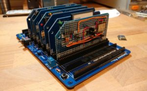
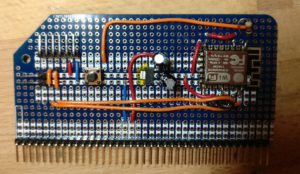
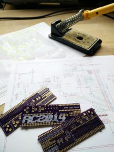
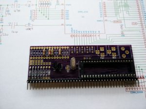
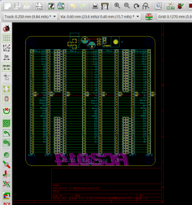
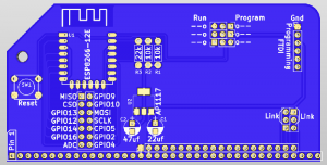
In other news, as I was happy enough with how the prototype PCB seems to be working, I’ve laid out a real board now.  The PCBs are currently being manufactured in China, although it isn’t looking likely that I’ll get them back before the end of this particular Retro Challenge.  But if I do, then expect an update here!  Here’s a sneaky peek at what they should look like though;


Retro Challenge 2017/10 Testing

The initial testing of the ESP8266 board with the RC2014 was pretty good, and fundamentally it worked.  However, it wasn’t quite right, and I suspected that the problem was to do with CR or LF.

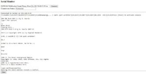
The code I was using was found here; https://github.com/tzapu/WebSocketSerialMonitor (Thanks Tzapu!).  It uses web sockets, and allows an external web page to connect through to the ESP8266.  So, by going to http://tzapu.github.io/WebSocketSerialMonitor/ and connecting to ws://x.x.x.x:81/ws (where x.x.x.x is my external IP address and a firewall rule is set up to forward port 81 through to the internal address of the ESP) it will display everything the ESP receives on its Rx pin.  Well, almost everything, but not quie everything.

If, for example, I did a directory listing which was 2 full lines and a little bit more on the 3rd line, only the first 2 lines would show up.  If I’m playing Zork, sometimes it would show the whole chunk of text as it came in, other times it would miss the last line.

The code itself is fairly easy to read, although the complicated web sockets stuff is hidden away in libraries.  This is the part of the routine that reads the serial input until it detects a CR (the ‘\n’ part), where upon it then sends the line;

void serialEvent() {
  while (Serial.available()) {
    char inChar = (char)Serial.read();
    if (inChar == '\n') {
      stringComplete = true;
      return;
    } else {
      inputString += inChar;
    }
  }
}

I figured that adding a check for a LF would do the job;

if (inChar == '\n' || inChar == '\r') {

But, sadly, it didn’t.  If anything, it made it worse.  So, instead, I tried just reading a set amount of characters (10 initially) and sending them regardless of a CR or LF, but that didn’t work either.  When I got it to send every character without checking, it worked much much better, although if I sent a very large chunk of text it would miss random bits of it.

So, the problem seemed to be speed related.  The checking for CR was a nice idea by the original author, but it wasn’t something I needed, so time to strip out all the surplus code.  It went from this;

void serialEvent() {
  while (Serial.available()) {
    char inChar = (char)Serial.read();
    if (inChar == '\n') {
      stringComplete = true;
      return;
    } else {
      inputString += inChar;
    }
  }
}


void loop() {
  serialEvent();
  if (stringComplete) {
    
    String line = inputString;
       // clear the string:
    inputString = "";
    stringComplete = false;

    //line += '\n';
    webSocket.broadcastTXT(line);
    Serial.println(line);
  }
  webSocket.loop();
}

to this;

void serialEvent() {
  while (Serial.available()) {
    char inChar = (char)Serial.read();
    inputString += inChar;
  }
}

void loop(){
  serialEvent();
  webSocket.broadcastTXT(inputString);
  inputString="";
  webSocket.loop();
}

Much simpler, and it seemed to work perfectly!

All the testing up until this point was done either on my laptop or mobile.  Although they are on the same wifi network as the ESP, it’s connecting out to an external web page before coming back in, so it should be a reasonable test.  But there’s nothing like real people connecting in to really see if it works.  So, I put a shout out on Twitter, and on Saturday evening, 4 willing volunteers sat there watching me do random things on the RC2014.

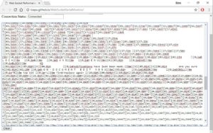
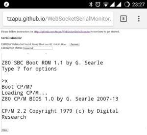
Feedback was pretty good, and it all seemed to work as expected.  Thanks Thilo for this screenshot;

I messed about with simple programs in BASIC, directory listings, and the opening moves in Zork, with success.  In a moment of madness, I fired up Wordstar.  When the RC2014 is connected to a VT100 terminal, it works great by using escape codes to set where things are on the screen and what colours are used.  However, these escape codes don’t render at all well on the web sockets interface.  Thanks Dave for showing my just how bad it looked!

So, yes, I should have known that Wordstar would be pushing it a bit far.  But otherwise, I was very pleased with the performance.

The biggest problem I had, though, was that of feedback when interacting with the “audience”.  I could type short sentences in to Zork that the viewers would see and understand, even if the Zork engine couldn’t interpret it.  But, of course, there was no live feedback from the viewers.

I’m not sure what the solution to that will be, but it could be as simple as keeping Twitter open on my phone.  Alternatively, things like IRC or Slack could be used (although I don’t want viewers to have to jump through hoops to get connected to me).  Skype might be an option too, although, at the moment, I think it’s more likely I’ll set up a YouTube live stream and use the chat feature in that.

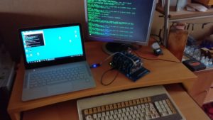
For those wondering about the set up that I’m using, it’s pretty much a stock RC2014 Pro with a Pi Serial Terminal and the ESP8266 prototype I built for this project.  The Pi Zero is connected via a HDMI > VGA adapter, and then to a 17″ monitor.  The keyboard is this Cherry keyboard from the last Retro Challenge.  Note that the key layout is sufficiently different from what I’m used to that typos aren’t too uncommon yet.

The laptop is there to program the ESP, and to monitor it’s output.

I am aiming to have a live run through on Friday, so that gives me a few days to look in to the feedback options.

Retro Challenge 2017/10 Getting Started

So, the idea of streaming the RC2014 to the internet had been rattling around in my head for a while, but I’d never quite worked out how the software side of things would work.  Although the hardware side should be kind of straightforward, with my software skills, I need to find something I can copy & paste.  A couple of days ago I just happened to put the right search terms in to Google and it gave a result that looked like it would do want I wanted.  So, with that, my plan for Retro Challenge took shape!

A couple of years ago I played around with some EPS8266 Wifi Modules, but never really found a use for them.  However, for this, they would be ideal.  The code I had found was a Web Sockets Serial Monitor designed specifically to run on an ESP8266, so I decided to test it out just to check that it did what I expected it would.

Several hours later, it did!  Those hours, however, were spent trying to remember how to program these things.  My desktop machine didn’t have any of the ESP stuff in the Arduino IDE, but luckily, I still have my old laptop that I used a couple of years ago.  Despite getting all the right libraries, it just wouldn’t compile.  So, on to the new laptop, with a fresh Arduino IDE and all the ESP stuff and libraries, and it compiles.  Getting it to upload, however, was another challenge which actually involved burning myself on the USB to serial adapter at one point!  It turns out that of the two I tried, one of them was dead, and the other one spammed my Twitter account ever time it’s turned on (I didn’t know this until checking Twitter later… what!  86 new mentions!).  It also turns out they need more power than the adapter can supply.  And, in order to program them, the ESP needs to be pushed in to the adapter really really really hard!

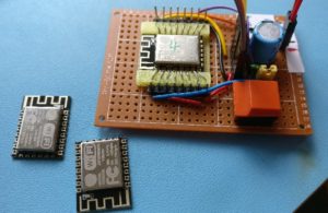
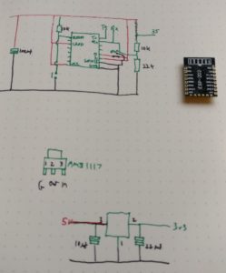
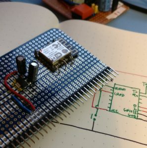
The programming jig wasn’t really suitable for testing things out, so time to transfer this to a prototype board.  But first, lets work out a circuit!  The programming jig has the necessary support components and minimal connections, so that’s a good start.  The ESP works on 3v3, so I’m going to need a regulator to drop the 5v down.  And the Rx pin is only 3v3 tolerant, so a couple of resistors as a voltage divider will work fine as a level shift here.  The Tx pin won’t be connecting to the RC2014, although even if it was needed, 3v3 is sufficient enough to work.  GPIO0 is used to either put the ESP in to programming mode or run mode.  2 of the other GPIO pins (15 and 2) were tide to ground and 3v3 respectively on the programming jig.  I can’t remember why I did that, but that won’t be needed for this board.

Before hooking up the ESP to the power rails, I checked that the regulator I used (spare one I had lying around) did it’s job.  Yup, 3.299v, close enough!  On with adding the rest of the stuff.

So, from left to right, we’ve got a connector for 3v3 so it can be powered directly if needed (or use 3v3 elsewhere), and an FTDI header for my 3v3 adapter so the ESP can be reprogrammed.  Then there’s a reset button, the 3v3 regulator and caps, then the ESP itself.  There’s a 10k pull up resistor on the reset pin, and a program/run jumper below the ESP.  As yet, the resistor divider for the Rx pin aren’t fitted.  But it should power up and work just as it did in the jig, right?

Ummm… no.  Regardless if I used the power regulator, or fed 3v3 in directly, out of the serial header all I got was gibberish.  It was consistent gibberish, but not something I could make any sense of.  Maybe I damaged the ESP when soldering the wires on?  Hmmmm… maybe I should program another one just in case.  Well, long story short, it needs GPIO15 connected to ground to work!  I can’t see any logic why this would need to be the case, but, whatever, it works now.

I needed to add a rule on the firewall to allow port 81 through to the IP address of the ESP, and after that, I could connect from the outside world and see what my RC2014 was saying!

Things work pretty well, although there’s some kind of issue with carriage returns and/or linefeeds that’s causing some stuff to be dropped, but that’s enough success for one day.  We’ll sort that out tomorrow!

Retro Challenge 2017

Ok, with 5 days of October already gone, I know it’s cutting things a bit fine for putting my entry in for this seasons Retro Challenge – particularly as it started 5 days ago… but, better late than never, right?

So, what have I planned to do that is both retro and challenging? Simple, I’m going to play games! More specifically, I’m going to play Zork, on a CP/M enabled RC2014 that is connected to the internet so it can be streamed live to an audience of anybody that cares to watch me get eaten by a grue.

The first challenge is going to be hooking up the RC2014 to the internet, such that it can stream text. Kind of like Twitch, but in ASCII. Luckily, I’ve got a bunch of ESP8266 modules that have been sitting in a drawer, and I think these are likely to be ideal for converting serial data in to web pages.  I should be able to hook up something on breadboard, and find a bit of code that does the job – although it would be nice if I can get some real PCBs made up for the job.  With just over 3 weeks to go, though, that might be pushing it timewise.

Then there is the challenge of Zork itself.  I often use it as a test game to show people what the RC2014 can do, however, I’ve never done more than a bit of random North, North, East, Look, Get Lamp etc.  I’ve never really played many text adventures either, so this will be a big learning experience for me.  I can’t promise that I won’t use the odd cheat/clue here and there, but if there are actually people watching along online, I’ll happily take suggestions over Twitter.  If things happen to go really well, and I complete it in good time, then I will add Adventure as a stretch goal.

Retro Challenge 10/2016 – Still a work in progress

So, who remembers my entry for Retro Challenge in January?  It was quite devoid of effort and results I think you’ll agree.

Well, this time around, I’ve taken that theme and pushed it even further!  Even less effort and much less result.

Since January, I have had a few opportunities to carry on with the ZX81 Module.  Because I wanted this to be a Retro Challenge project, I deliberately avoided doing any work on it, so I could save it all for October.  Well, October started and I was overwhelmed with non-Retro Challenge stuff.  But after a couple of weeks, I had a spare afternoon, and decided to dedicate this to the ZX81 Module!

So, I dug out the PCBs I had manufactured in January and fired up the soldering iron;

retrochallenge10-2016_1

Time to wrack my brains and work out what my plans had been 9 months earlier.  I had failed to put any component values on the PCB, or even my Kicad schematics, so had to rifle through original ZX81 schematics to work out what these should be.

Now I knew what components I needed, it quickly dawned on me that I didn’t have very many of these at all.  This didn’t deter me though.  I fitted everything I had; IC socket, pin headers, some resistors and some transistors that may or may not be compatible;

retrochallenge10-2016_2

And that’s about it.  I have ordered the rest of the parts now, but not had an opportunity to fit them.  yet.

One thing I have learned from this experience though, is that if I get any opportunity or urge to work on this, then I will seize it.  Not wait until the next Retro Challenge.  If I’d done work on this months ago when I had the chance, then this would more likely be a trouble shooting / tweaking / developing challenge.

One other good thing that has come out of this though, is that when I started this in January, I had a few design changes or additions required for the RC2014 for it to work.  The Backplane 8 has the ability to add resistors between the CPU and the RAM.  The Universal Micro Keyboard has the right connections to work with a real ZX81 or this ZX81 Module (including diodes).  The CPU Module also now has BUSRQ, WAIT, NMI and WAIT pins broken out which is required for this.  These changes should all make things much easier.

Despite my poor efforts this time around, I have thoroughly enjoyed seeing what everybody else has achieved with their Retro Challenge.  Good work everybody else!

Retro Challenge 2016 – My Dog Ate My Homework

So, all the way back in deepest darkest December, I announced I would enter the Retro Challenge 2016 competition that ran throughout January.  Those of you that followed by blog or Twitter account when I did this in 2014 will know that I blogged and Tweeted relentlessly for the whole month, but, this time around, almost nothing.  Obviously, I’m keeping some secret about an amazing breakthrough or something, right?  Well, truth is, I’ve done almost nothing.

Things started well, and on 1st January, I designed a new backplane for the RC2014.  Although I hadn’t studied the circuit diagrams for the ZX81, Jupiter Ace or ZX Spectrum yet, I knew that there were resistiors between the Z80 CPU and other devices.  The stripboard backplane I’d been using had served me well, but it was time to progress to a better solution, and one that could be adapted better to my needs.  Knowing that PCB delivery times could be against me, I thought it best to crack on and get this  ordered.

Screenshot from 2016-01-31 16:01:00

The basic circuit is very very simple – however, I wanted to get this just right, not only for Retro Challenge 2016, but for other possible RC2014 uses.  Essentially, there are 8 40 way connectors that are linked straight through – however, the data lines and address lines for the leftmost 2 connectors and rightmost 2 connectors are separated by a pair of pads.  These can either be shorted together for up to 8 commoned connectors, or have resistors soldered across them.  I also added a power connector and the option of either running 5v directly in to the board, or regulating a higher voltage down via a LM7805.

(more…)

HDMI and USB Keyboard Support

So, the RC2014 is a great little computer.  We all know that.  However, to communicate with it, it is easiest to use the serial port and hook it up to a laptop or desktop PC.  This makes detracts from the fact that it is small, portable and cheap as well as missing the point of running code on such a basic computer.  So I’ve been looking for a solution to this.

Back when this was still running on a breadboard, I hooked up an Atmel ‘328 that was connected to a keyboard and 4 x 20 LCD display.  It communicated with the RC2014 over the serial port and kind of worked ok, although 4 lines was very restrictive and the Atmel couldn’t really keep the screen running and listening at the same time.   I have thought about using a ‘328 to drive a composite output, or maybe some kind of bigger LCD panel, but nothing really struck me as just right.

That is, until the kind people at Raspberry Pi released a cheap multifunction interface device a couple of weeks ago!

2015-12-18 22.13.44

(more…)

Retro Challenge January 2016 – Preamble

So, you may well remember that I entered Retro Challenge 18 months ago, and what a fun crazy busy time that was!  Well, the January Retro Challenge competition is about to kick off in just over 2 weeks.

If you’re not familiar with Retro Challenge, shame on you!  But you can de-shame yourself by heading over to http://www.retrochallenge.org/ and seeing what it’s all about.  Essentially, it’s a month long bi-annual competition where the entrants set themselves a goal based around old school computing and blog, tweet and share their experiences.  The goals are pretty loose, as long as they are based on something from last centuary (modern emulators of old kit is fine).

The challenge I set myself was to take a breadboard based Z80 computer and bring it to life in modular PCB form in such a way that I could spell out my name on.  Have a look back through my blog to see how I did.  Spoiler —->

IMG_20140730_205950

(more…)

RC2014 Bootloader for SD Cards

So, the RC2014 is great.  I can run Microsoft BASIC and program it from there, and as long as I am using a terminal emulator, I can copy & paste to save and load programs.  Alternatively, I can write Z80 code using an online compiler then download it, copy it to USB stick, move it to my old Windows 2000 laptop (which has a parallel port) so I can burn it on to EPROM to see if it works, make adjustments and repeat with another EPROM.

I will be the first to admit, however, that this is probably not the most efficient workflow.  Not to mention the time and effort involved in wiping the limited stock of aged EPROMS.

So, I am in the process of designing an SD Card based bootloader.

i (2)

(more…)

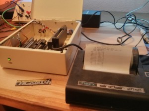
RC2014 with ZX Printer interface

My original plan had never been to design and build my own computer.  I had, however, planned to build a clone of the Sinclair ZX80, which has been on my bucket list of things to own for year, and which I had found plans for online.  Whilst collecting the parts and reading up on simple Z80 computers I got kind of sidetracked and ended up with the RC2014.

The print out shown was what was left from the last time this was connected to a ZX Spectrum!

The heart of the RC2014 is a Zilog Z80 CPU, which is the same one that Sinclair used in the ZX80, ZX81, ZX Spectrum and Z88.  If the ZX81 and ZX Spectrum can run a ZX Printer, then surely it follows that the RC2014 will be able to too?

(more…)